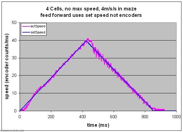
As set up for the last post, my micromouse Decimus is performing reasonably well on the ground. So far. The data plots show some features that are a little bit curious. However, my concerns over the apparent error in the endpoint were a little misleading. The recorded error is derived from the integral of the set speed and the total count from the wheel encoders. Thus, it does not represent an actual error on the ground…
This may not make much sense but the distances according to the set speed are representative of what the profiler thinks should be happening. That is to say, the profiler takes the desired speed and acceleration and uses them to derive a set speed for the mouse. This is used to tell the motor controller where the wheels should be. It is a relative term. Actual distance on the ground is measured from the encoders. And, so far, the mouse position on the ground is correct to less than the error shown on the graph. Effectively, the error plots just say how hard the controller wants to drive the motors. As with any control system, without an error there will be no restorative force.
One of the features that is interesting is the oscillation after turn-around when we switch from accelerating to decelerating in a couple of milliseconds. This is a big change. Possibly the biggest and may well represent the hardest work the controller has to do. Another feature is that the position error seems to reduce as the mouse gets faster. Now this may be due to the controller being under damped or it may be due to an incorrect value for the speed related feed forward term.
When a motor is turning, it generates a voltage that opposes any more current flowing in to it. This is the reason that a motor runs at a given speed for any particular applied voltage. Consequently, when the motor is running quickly, we need to take into account that back emf by applying an even higher voltage to the motor if we want to change its speed. Decimus does this. A value for the PWM is calculated according to the error terms and then an additional value is added that is proportional to the motor speed. In the last trial, I was using the actual motor speed as measured by the encoder counts. This is a bit crude and there is an implicit error of +/- half a count even at best. A simple change is to use the set speed which is maintained to a higher precision.
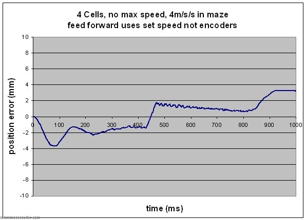
It is clear that this has reduced the oscillation somewhat. It has had the effect of filtering the applied feed forward term. After seeking some expert advice, it was suggested that the value of the speed feed forward term might be a bit high. As it stands, the term is calculated from the published motor specification. I need to determine a value experimentally that is better suited to the actual motors I have. Out of interest though, I ran the same trials with significantly larger and smaller values of the back emf constant.
First, the constant was lowered from 3840 to 2840. As this is a signed 8.8 fixed point number, this is a reduction from 15 to 11. A very big change but I wanted to see how much effect the term had.
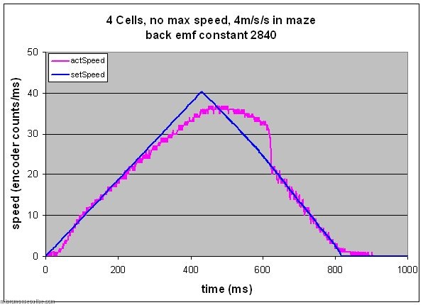
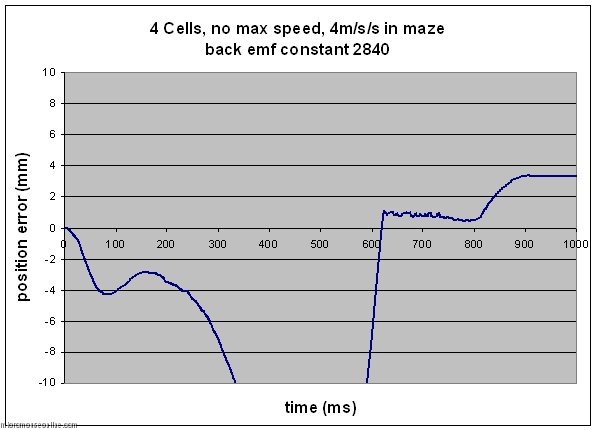
Wow! Now the response is just rubbish. Well, not quite but it is pretty poor. The finishing position of the mouse on the ground overshoots by 15mm or so even though we get the same apparent error from the data. The reason for this is probably the huge deceleration at about 600ms. At that point, the tyres will almost certainly slip and the mouse will slide on effectively out of control. This is a valuable lesson. I had seen a tendency for the mouse to overshoot when the acceleration was turned up and now I understand why. It was not the high acceleration as such but at that time, I had no feed forward control term. This will drive the controller to extremes in an attempt to eliminate the errors. The resultant skid is invisible to the observer. You can barely see what it is doing anyway. Even filming them doesn’t help much. For these trials, the entire sequence would be over in about 20 frames with a PAL camera (25 frames for the NTSC world). The high speed performance is the thing to notice. As the mouse gets fast, the controller is unable to generate a high enough voltage to keep accelerating the mouse.
So, the obvious question now is – what happens if we use too much feed forward. For the next trial, the constant was increased from 3840 to 4840:
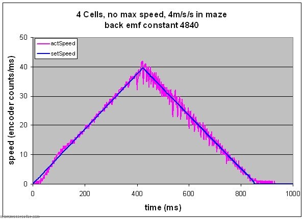

Once again, the initial and final phases of movement are pretty well unchanged but there are differences at high speed. Most obviously, the decelerating phase is much more noisy than before although the position error is not degraded too severely. I think. I really don’t understand where this noisy response comes from. Bear in mind, the controller gains have never been properly set so until that is done everything is a bit of a guess. The frustrating thing is that the acceleration portion behaves pretty well exactly how I would predict. The other feature is that the speed of the mouse (on average) more closely follows the set speed at the point of change over.
More testing …
After a good number of trials, I have found a value for the back emf feed forward constant that seems to improve matters considerably. It is still a bit too big but that is safer than having it too small. Tests in tiny maze sections don’t tell you what will happen at speed. In particular, the speed compensation may work just fine at the relatively low speeds found in the maze but you don’t want it to all go pear shaped when you hit a long straight. Since I only have a 5×5 maze, I was forced to clean a bit of the kitchen floor and test it in there. The surface is different to a maze but it is hard and smooth. I think that if I can get 4m/s/s in the kitchen, a reasonable maze should be fine. Decimus has a designed-in top speed of 2.8m/s. This is an arbitrary figure that is based on all the losses I think are in the system and assumes a battery voltage of at least 6.5V as a worst-case. If I chose 7.2V for the battery voltage, I should be able to do 3m/s. At this stage, better safe than sorry. It takes 0.7 seconds to reach 2.8m/s by which time the mouse has travelled 5.4 squares so I set the run for a total of 12 squares. I only have room for 1000 data samples so the plots are truncated.

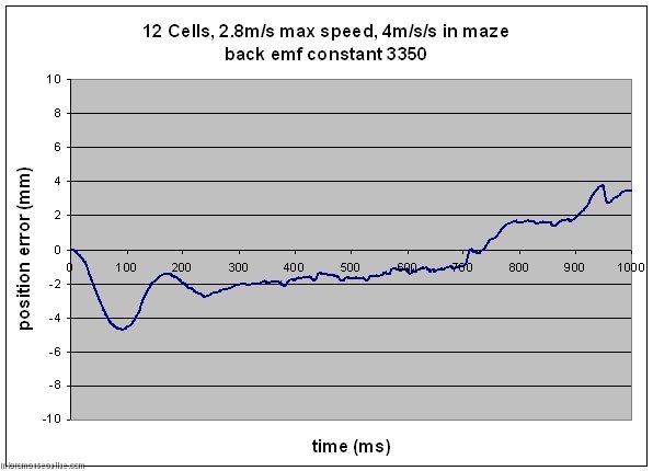
Even a change in speed compensation of 0.1 changes the behaviour from stable to unstable so I am not going to tune this any further for the time being until I can get in a real maze. The problem now is that so many of these constants inter-relate and I don’t have a good enough mathematical model to let me predict exactly how. Even if I did, there would still be a need for much empirical testing.
A final point occurs. During the initial phase, the mouse is trying to catch up with the controller and is eventually forced to accelerate harder than the design value in order to do so. This is a potential source of trouble should the mouse lose grip at that point. The same will happen at the changeover points. Either proper tuning of the controller will help reduce this or it may become necessary to introduce a smoother change in acceleration at those points.
Hi Peter,
I was hoping you could help me with getting a feedforward component set up? Or point me towards a good reference.
Currently I have two controllers, one for lateral, one for rotational. They both output a PWM value strictly based on a PD controller, with the input being encoder counts. The controllers are used by two profilers that generate the setpoint at each interval.
So from this article, it seems that my controller should only use encoders to “fine tune,” and the majority of the PWM output should come from the feedforward?
If so, do I simply have something along the lines of:
PWM_out = setspeed/k_FF + k_P*error+k_D*delta_error;
so far, that has not been working out. Please suggest what to do 🙂
Thank you for your time and assistance!
Apologies for the delay in responding.
Here is the code that I use to determine the feedforward values for the forward controller:
// now do the feedforward
  oldFwdSpeed = newFwdSpeed;
  newFwdSpeed = fwd.currentSpeed;
  acceleration = newFwdSpeed - oldFwdSpeed;
  feedforward = (newFwdSpeed * FWD_SPEED_FF) / 65536;
  if (acceleration > 0) {
    feedforward += (FWD_ACC_FF * acceleration) / 256;
  } else {
    feedforward += (FWD_DEC_FF * acceleration) / 256;
  }
  if (newFwdSpeed > 0) {
    feedforward += FWD_STATIC_FF;
  } else if (newFwdSpeed < 0)  {
    feedforward -= FWD_STATIC_FF;
  }
  leftffwd = feedforward;
  rightffwd = feedforward;
There are three components to the feedforward. One for speed, one for acceleration and one for overcoming any static friction or other losses in the drive train. Clearly, you will have to determine these constants by experiment for your mouse.
A similar process is used to determine the rotational values for each wheel. Remember that, for rotation, one wheel will have the feedforward added, the other will have it subtracted.
The feedforward value for each wheel is then just added to the PWM calculated from the controller.
The fwd.currentSpeed variable is the speed as set by the profiler - not the speed as measured at the wheels. This means that you should be able to set the controller output to zero and have just the feedforward values sent to the motors. If you have the constants right, the mouse should make a fairly good job of completing the move requested.
Hi Peter,
Wow, thank you for that comprehensive answer, it really is helpful. Hopefully I will be able to
implement this.
Also, my understanding is that using feedforward eliminates the lag normally needed to cause
a drive from the motor controller? Does that make that much of a difference?
Thanks!
void feedfoward (int n_r, int n_l, float baterry_voltage){
//n é o número de rotações no motor e pode ser encontrado a partir do valor de contagem do encoder
float t_tire; //torque do pneu
float t_motor; //torque do motor
float current; //corrente no motor
float motor_voltage_r,motor_voltage_l; //tensão necessária no motor
float counter_emf_r, counter_emf_l; //força contra eletromotriz no motor
int r_duty, l_duty;
t_tire = MACHINE_WEIGHT * MACHINE_MAX_LINEAR_DECELERATION / 2 * MACHINE_WHEEL_RADIUS;
t_motor = t_tire / GEAR_RATION;
current = t_motor / MACHINE_TORQUE_CONSTANT;
counter_emf_r = MACHINE_VOLTAGE_CONSTANT * n_r;
counter_emf_l = MACHINE_VOLTAGE_CONSTANT * n_l;
motor_voltage_r = MACHINE_MOTOR_RESISTANCE * current + counter_emf_r;
motor_voltage_l = MACHINE_MOTOR_RESISTANCE * current + counter_emf_l;
//Ao controlar o motor de fato, a relação de trabalho r_duty da onda PWM é alterada
r_duty = abs(motor_voltage_r / baterry_voltage);
l_duty = abs(motor_voltage_l / baterry_voltage);
}
void setPIDParameter(float pvX, float pvW, float speed_x, float speed_w) {
float pos_pwm_x;
float pos_pwm_w;
erro_pos_x += speed_x – pvX;
erro_pos_w += speed_w – pvW;
pos_pwm_x = KP_X * erro_pos_x + KD_X * (erro_pos_x – old_error_pos_x);
pos_pwm_w = KP_W * erro_pos_w + KD_W * (erro_pos_w – old_error_pos_w);
old_error_pos_x = erro_pos_x;
old_error_pos_w = erro_pos_w;
pwm_l = pos_pwm_x – pos_pwm_w;
pwm_r = pos_pwm_x + pos_pwm_w;
}
Hello peter i’m doing a line follower robot and i want to implement a feedforward control but i’m not knowing how to do so, i was looking that some people have i KPff constant to their feedforward controller, how this constant is tunning?
And where the pwm calculate by the feedforward control goes? I’m not finding many content about feedforward in micromouse/robotracer, and i would be really happy if you could help me, thanks in advance by your consideration and attention!!
There are several ways to do feedforward control. The basic idea is to work out what voltage you would need to apply to the motor(s) to get the desired response, even if there were no controller active. There will be a voltage proportional to speed and an additional voltage needed to push accelerating current through the motors.
I determine the constants by experimentation. Run the robot with a series of different open-loop voltages and with the controllers turned off. Record the steady-state speed and you can plot a chart of voltage vs speed. The slope of that graph is the speed feedforward constant. The intercept is the bias voltage needed to get the motors moving. If, for each voltage, you plot the entire speed response over time, you can estimate the acceleration feedforward constant from the initial slope of the responses.
For fine tuning, have the robot perform some movements and record the controller output voltage – not the motor voltage, just the controller response. If the feedforward voltages are well tuned, the controller will have almost no work to do and the output will be zer0.
You appear to have modelled the motor in your calculation and it looks reasonable at first glance. It looks like all you need to do is add the calculated duty to the pwm_l and pwm_r values. Be aware though that you are only accounting for the forward motion of the robot.
For comparison, the final stage of the motor calculations for my robot is:
//========================================== // Combine the components leftMotorVolts = 0; leftMotorVolts += fwdControllerVolts - rotControllerVolts; rightMotorVolts = 0; rightMotorVolts += fwdControllerVolts + rotControllerVolts; if (fwdFFControlEnabled) { leftMotorVolts += fwdFeedForward; rightMotorVolts += fwdFeedForward; } if (rotFFControlEnabled) { leftMotorVolts -= rotFeedForward; rightMotorVolts += rotFeedForward; }OH thank you very much peter for the answer, that helps a lot, i will try to do some tests, thank you!