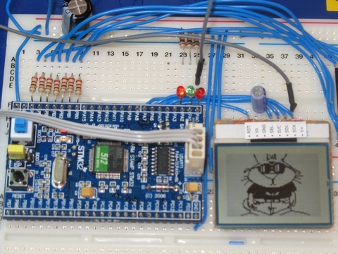
 The Nokia LCD displays are among my favourite toys. Generally, I use a monochrome display intended for the Nokia 3410 ‘phone. This a display size of 96 x 48 pixels and can display bitmaps as well as text in 6 rows of 16 characters. It is smaller than the more common 16×2 text-only displays, easier to drive, cheaper, uses fewer connections, much more flexible and is readily available. And now, I have connected one up to my STM32F103 Cortex-M3 processor. As a first go with the SPI peripheral on these processors, it has been quite instructive…
There are plenty of other places to go and find out about he Nokia displays SPI in general. There is a short list at the end of this post. Here I just want to look at the business of getting the SPI going on the STM32. As with the other examples here, I have used the ST Peripheral Driver Library and its functions relating to the SPI peripheral. No attempt has been made to bypass these to talk to the hardware as they are fast enough for my purposes and give the promise of some portability.
For this example, the LCD is connected to the SPI1 port which uses pins on Port A. These are:
| Pin name | SPI Function | Nokia Function | ||
|---|---|---|---|---|
| PA4 | SPI1_NSS | Display Select | ||
| PA5 | SPI1_SCK | Serial Clock | ||
| PA6 | SPI1_MISO | Data/Command | ||
| PA7 | SPI1_MOSI | Serial Data | ||
| PA3 | none | Display Reset |
The SPI functions of these pins are in the alternate function set. that is, after a reset, the pins work as plain GPIO pins so the appropriate settings need to be made to the port. the Nokia display is a write-only device so there is no use for the MISO pin and it can be used as a GPIO to drive the Data/Command select pin of the display. Similarly, the Slave Select pin, SPI1_NSS, will be set in software and so can be left as a GPIO. That leaves only two of the dedicated SPI pins used for their SPI function. First then, the ordinary GPIO pins are configured:
SPI_InitTypeDef  SPI_InitStructure;
  GPIO_InitTypeDef GPIO_InitStructure;

  /* Enable SPI1 and GPIO clocks */
  RCC_APB2PeriphClockCmd( RCC_APB2Periph_SPI_NOKIA, ENABLE);
  RCC_APB2PeriphClockCmd(RCC_APB2Periph_GPIO_NOKIA, ENABLE);

  GPIO_InitStructure.GPIO_Pin = GPIO_Pin_CS | GPIO_Pin_DC | GPIO_Pin_RST;
  GPIO_InitStructure.GPIO_Speed = GPIO_Speed_50MHz;
  GPIO_InitStructure.GPIO_Mode = GPIO_Mode_Out_PP;
  GPIO_Init(GPIO_LED, &GPIO_InitStructure);
Then the Alternate function is setup for the SCK and MOSI pins:
  /* Configure SPI1 pins: SCK and MOSI only to their Alternative (SPI) function */
  GPIO_InitStructure.GPIO_Pin = GPIO_Pin_SCK | GPIO_Pin_MOSI;
  GPIO_InitStructure.GPIO_Mode = GPIO_Mode_AF_PP;
  GPIO_InitStructure.GPIO_Speed = GPIO_Speed_50MHz;
  GPIO_Init(GPIO_NOKIA, &GPIO_InitStructure);
At this point, the display can be initialised by holding down the reset line for at least 10us. The Chip select is normally left high in case anoher peripheral is sharing the SPI port.
/* Deselect the display Chip Select high */
  SPI_NOKIA_CS_HIGH();
  SPI_NOKIA_RST_LOW();
  delay(100000);
  SPI_NOKIA_RST_HIGH();
Finally, the SPI port itself is configured:
  /* SPI1 configuration */
  SPI_InitStructure.SPI_Direction = SPI_Direction_2Lines_FullDuplex;
  SPI_InitStructure.SPI_Mode = SPI_Mode_Master;
  SPI_InitStructure.SPI_DataSize = SPI_DataSize_8b;
  SPI_InitStructure.SPI_CPOL = SPI_CPOL_High;
  SPI_InitStructure.SPI_CPHA = SPI_CPHA_2Edge;
  SPI_InitStructure.SPI_NSS = SPI_NSS_Soft;
  SPI_InitStructure.SPI_BaudRatePrescaler = SPI_BaudRatePrescaler_16;
  SPI_InitStructure.SPI_FirstBit = SPI_FirstBit_MSB;
  SPI_InitStructure.SPI_CRCPolynomial = 7;
  SPI_Init(SPI1, &SPI_InitStructure);
  /* Enable SPI1  */
  SPI_Cmd(SPI1, ENABLE);
This code is taken straight out of one of the ST example programs. Notice that the SPI runs as a master device with a clock divisor of 16 which gives a clock rate of (72/16) = 4.5MHz. Also, the NSS line is set for software control. I didn’t check the SPI mode used by the port but it is correct for a Nokia 3410 display. Also lifted from an ST example was the code needed to send an 8 bit value to the display. However, this seemed to have a bit of a problem. This is similar to the issue I have had with the SPI peripheral on the dsPIC. The routine started by waiting until the transmit buffer was empty before trying to dump the byte into it. That is a precondition but, with a slow SPI clock, it was possible to load up the buffer before the preceding transfer was finished. That would cause the final test to return prematurely and the caller would release the slave select line before the slave had got all the data. What is really needed is a way to tell if the transmit shift register is empty. On the face of it, waiting for the receive buffer to fill should do the trick but if it has not been read after a previous transfer, the RXNE flag will still be set, the test succeeds and the previous value is read while the current one carries on shifting in. As a temporary fix, I added a single line to the beginning to perform a dummy read from the receive buffer and reset the RXNE flag:
/**
  * @brief  Sends a byte through the SPI interface and return the byte
  *   received from the SPI bus.
  * @param byte : byte to send.
  * @retval : The value of the received byte.
  */
u8 SPI_NOKIA_SendByte(u8 byte)
{
  SPI_I2S_ReceiveData(SPI1);
  /* Loop while DR register in not emplty */
  while (SPI_I2S_GetFlagStatus(SPI1, SPI_I2S_FLAG_TXE) == RESET);
  /* Send byte through the SPI1 peripheral */
  SPI_I2S_SendData(SPI1, byte);
  /* Wait to receive a byte */
  while (SPI_I2S_GetFlagStatus(SPI1, SPI_I2S_FLAG_RXNE) == RESET);
  /* Return the byte read from the SPI bus */
  return SPI_I2S_ReceiveData(SPI1);
}
This works although I am not happy about it. It seems like a terrible kludge and I shall have to find a more elegant way to do this. The return value will be ignored as nothing gets sent back from the display but it is kept here as a reminder for any other use at a later date. Data sent to the display will be either a data byte or a command byte. Here are the two functions that do that:
void nokiaCmd( int c )
{
  SPI_NOKIA_CS_LOW();         // Select the device
  SPI_NOKIA_DC_LOW();         // sending command
  (void)SPI_NOKIA_SendByte( c );
  SPI_NOKIA_CS_HIGH();         // Deselect the device
}

void nokiaData( int c )
{
  SPI_NOKIA_CS_LOW();         // Select the device
  SPI_NOKIA_DC_HIGH();        // sending data
  (void)SPI_NOKIA_SendByte( c );
  SPI_NOKIA_CS_HIGH();        // Deselect the device
}
the control line toggling is done with a set of macros:
#define SPI_NOKIA_CS_LOW()        GPIO_ResetBits(GPIO_NOKIA_CS, GPIO_Pin_CS)
#define SPI_NOKIA_CS_HIGH()       GPIO_SetBits(GPIO_NOKIA_CS, GPIO_Pin_CS)

#define SPI_NOKIA_DC_LOW()        GPIO_ResetBits(GPIO_NOKIA_DC, GPIO_Pin_DC)
#define SPI_NOKIA_DC_HIGH()       GPIO_SetBits(GPIO_NOKIA_DC, GPIO_Pin_DC)

#define SPI_NOKIA_RST_LOW()       GPIO_ResetBits(GPIO_NOKIA_RST, GPIO_Pin_RST)
#define SPI_NOKIA_RST_HIGH()      GPIO_SetBits(GPIO_NOKIA_RST, GPIO_Pin_RST)
The rest of the display code is all well proven and I have been using t for some time. it is based on code originally written, I think by Sylvain Bissonnette. Try these references for more information about the Nokia 3310/3410 displays:
- SPI data transfers
- LCD screen for Decimus
- Adding a timer and the graphical LCD
- Nokia LCD Lib
- Nokia 3310 LCD
- Nokia 3310 LCD, 84×48 pixels
Updated 27th May 2009 to correct a bug in the SPI_NOKIA_SendByte() function where slow SPI clocks could cause the slave select line to be released prematurely.
I have a fix for your dummy read problem. If, as you are in this example, transmitting data only, you may configure the SPI for 1 line TX as follows:
/* SPI configuration */
SPI_InitStructure.SPI_Direction = SPI_Direction_1Line_Tx;
SPI_InitStructure.SPI_Mode = SPI_Mode_Master;
.
.
.
Then, in your send function, before asserting CS and before de-asserting CS check the status of the BUSY flag instead of the TXE flag. Otherwise, you will de-assert CS before all of the data is shifted out of the MOSI pin.
     /* Loop while BUSY in communication or TX buffer not emplty
      * before selecting the AD5621
      */
     while (SPI_I2S_GetFlagStatus(SPI1, SPI_I2S_FLAG_BSY) == SET);
     csLOW();

     /* Send 16-bit word through the SPI1 peripheral */
     SPI_I2S_SendData(SPI1, data);

     /* Loop while BUSY in communication or TX buffer not emplty
      * before deselecting the AD5621
      */
     while (SPI_I2S_GetFlagStatus(SPI1, SPI_I2S_FLAG_BSY) == SET);
     csHIGH();
Enjoy!
Tom
Thank you.
I will have a look at that and give it a try over the weekend.
before i start let me tell you i am a complete novice.so it would be helpful if you reply in simple steps that i can understand.
i have a display lcd from EA DOGM162L-A whose data sheet can be found at
http://nl.mouser.com/ProductDetail/ELECTRONIC-ASSEMBLY/EA-DOGM162L-A/?qs=s9z6UkyjM7oV4999Q8yEyQ%3d%3d
(in the documents tab).
i have to get the display to show hello world and i want to use the SPI interface to do it.so i soldered the display to the board so that i use the SPI2 interface according to page 4 of the display data sheet(3.3V SPI).
following the initialisation sequence in the data sheet,i understood i have to first write the data 55H into the display ram so that i can get the display to start.
also i have downloaded the stm32 standard peripheral library from stm site from
http://www.st.com/mcu/modules.php?name=mcu&file=devicedocs&DEV=STM32F103RB#Firmware
so my present trouble is
1)how do i get the spi2 driver installed from the library i downloaded(is it necessary to install at all?)
2)once i resolve the SPI issue how can i proceed to write data 55H to display ram so that my display can come to life
3)this is the final objective, how do i get the hello world printed on the display?
i know this may not be what you are working on right now, but i thought you must have some idea about initializing new interface from your experience.please help
I cant offer much help on other display devices. However, for the STM32 peripheral library, you might like to check this post and, moe importantly, the comments:
https://micromouseonline.com/sites/default/files/2009/05/18/stm32-on-the-mac-the-st-peripheral-driver-library
hello peteh,
I have read ur post as i am working on the same board but a different display.however my questions are regarding the board.this might be a long post and so i request your patience.
u8 SPI_NOKIA_SendByte(u8 byte)
{
  SPI_I2S_ReceiveData(SPI1);
  /* Loop while DR register in not emplty */
  while (SPI_I2S_GetFlagStatus(SPI1, SPI_I2S_FLAG_TXE) == RESET);
  /* Send byte through the SPI1 peripheral */
  SPI_I2S_SendData(SPI1, byte);
  /* Wait to receive a byte */
  while (SPI_I2S_GetFlagStatus(SPI1, SPI_I2S_FLAG_RXNE) == RESET);
  /* Return the byte read from the SPI bus */
  return SPI_I2S_ReceiveData(SPI1);
}
the above code has been changed by me to meet my SPI2 interface however i have some problem understanding the code as this is the first time i am using the board.so i want to know
1)the return type being u8 the function returns a data byte.but as the display is a one side data transfer, what does the board indeed “receive”?
2)regarding the first line of subroutine,
SPI_I2S_ReceiveData(SPI1);what exact data this it receiving from the display? the comments in the peripheral file was not in detail .so i need your help understanding it.it would be great if you can give me the entire function description in detail.
3)you have used software chip select insted of hardware.now since i have only 1 slave device, and i think even you had only 1 slave device, why did you choose to use a software NSS instead of Hardware?
4)If we use the hardware chipselect for SPI initialisation, can we forget about writing a code for making the chipselect low and again making it high.for hardware chipselect, is the chipselect pin automatically made low each time data is sent and high after date transmission is finished? or should we code it ourselves?
5)then for the final question, i used the software NSS as you used and sent a data 39H from the MOSI pin.i scoped the output and saw that after the last bit which is “1”, is sent, the pin remains high till next bit is “0” if this “0” comes after a delay time(which is required for initialisation of display), then all through the delay, the pin remains high.how do i stop this as i am sending meaningless bits to the display in the delay time.i am afraid this is why the display is not starting even after sending the correct intitialization sequence.
Hi – sorry for the delay…
Nothing is returned from the nokia display. The code is simply copied from some other SendByte function in the library or an example – I forget where.
I have not looked at this for a while but you can probably leave that out. However, the first read simply makes sure that the SPI peripheral is in a suitable state to send. It too could probably be left out but I would want to have a good look at what is going on first.
I use the software slave select because I have had configurations with more than one SPI slave. Also, in a previous version of the code on a Microchip Processor, the hardware slave select did not function correctly so I ended up doing it in software.
The state of the MOSI pin should only be read by the display of edges of the SPI clock signal. It should not matter what the state of the MOSI line is at any other times.
Thanks for the STM32 SPI info – it should really be helpful for my open source watch project, (more details arriving soon at http://www.meadtimemachines.com) which until now I’ve been developing on a Raisonance STM32 Primer2. Unfortunately, I can’t use the cheap and widely available 3310 display in my watch as it’s a little large and has too few pixels, but the principles you cover should be useful.
Also, you might like to know the following three links at the bottom of your article are dead: |SPI data transfers LCD screen for Decimus |Adding a timer and the graphical LCD |Nokia LCD Lib.
Hi
Thank for your comments. I have repaired the broken links.
Hi peteh,
if you’re still messing about with small displays, you might be interested in checking out the latest Sharp Memory LCDs.
I’ve just got one of their Silver Metallic Polymer Network Liquid Crystal Modules (PLNC) 96×96 displays working, connected to an Energy Micro EFM Tiny Gecko STK3300 (starter kit). The display looks really bright and clear – and power consumption is down in the micro-watt range. A little more expensive than the early Nokia displays, they are however available through Mouser, (I paid GBP 14.41 ea for P/n LS013B4DN02) and others in ‘each’ quantities – which is pretty amazing for latest technology display solutions in these sizes. Adafruit.com featured them recently too, so maybe they’ll also be stocking them soon.
I can’t say enough good about EM’s support or their dev kit either. For a recent start-up, they’re moving at a staggering pace.
It’s taken way longer than expected, but I’m still aiming to release an open-source watch module based on the EM Gecko and Sharp display – fingers crossed it’ll be just in time for some publicity from the Baselworld Watch and Jewelery Show, 8 – 15 March 2012.
I’ll be posting some code here on github very soon – just as soon as it’s half presentable.
Thanks again for your inspiration.
Hi,
I’ve got problem with configuration my nokia 3410 LCD + STM32L-DISCOVERY. Can you write commands which you send to LCD? How can I know that I correctly initialised LCD?
Thanks in advance.
Regards
I solved my problem. This is what I sent to LCD:
LCDN_SPI_Transmit(0x21); //Extended instruction set (H)
LCDN_SPI_Transmit(0xC0); //Vop setting
LCDN_SPI_Transmit(0x06); //Temperature Coefficient
LCDN_SPI_Transmit(0x13); //Set bias system
LCDN_SPI_Transmit(0x0A); //HV-gen voltage multiplication
LCDN_SPI_Transmit(0x20); //H=0 <- Basic Instruction set
LCDN_SPI_Transmit(0x11); //VLCD Programming range
LCDN_SPI_Transmit(0x0C); //display configuration
LCDN_SPI_Transmit(0x40); //Set Y-Address of RAM (=0)
LCDN_SPI_Transmit(0x80); //Set X-Address of RAM (=0)
Hi,
i try to implement this on the STM32F107 with a Nokia 6610 LCD with Epson Microcontroller.
I could not get it work yet.
My question is:
If you configure the MISO pin of the Microcontroller as GPIO and send the Data/Command bit out from it, don’t you have to do some extra clocking to for that bit?
The Bytes you send with SPI_I2S_SendData are clocked, since they go from the SPI_TDR, but I don’t understand how this bit was clocked at the LCD.
Would appreciate a short answer.
Thank you,
Dincer
“SPI_NOKIA_DC_LOW(); // sending data” probably a typo in nokiaCmd method comment – should be “sending command”?
Anyway, this is a great article and it has helped me a lot to get another LCD working over SPI! Thanks a log.
Quite right. Fixed now, thank you.
I have a problem to get my 3310 LCD works !
I’ve done almost the same thing and i got nothing…would you help me Peter ?
With a bit of luck someone reading this can help out. I am really tied up preparing for the contest at APEC for a week or two. Perhaps when I get back? Sorry.
Hmm my display works with different SPI settings: CPOL_Low and CPHA1Edge