A USART is a universal synchronous asynchronous receiver transmitter. A serial port if you like. On the STM32 however, it really is universal. This peripheral has a raft of features for a huge range of serial protocols including all the usual asynchronous modes plus IrDA, LIN, Smartcard Emulation and the ability to function as an SPI port…
Typical STM32 parts have between 2 and 5 USART peripherals. The STM32F103RE is described as having 5 USART/UART devices. USART1 live on the high-speed APB2 bus while USART2, USART3, UART4 and UART5 are connected to the lower-speed APB1 bus. The UARTs differ from the USARTs in that they do not provide hardware flow control or synchronous operation or smartcard emulation. All other functions appear to be supported [RM0008 – sec 25.5].
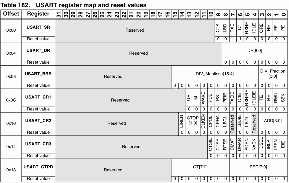
It will come as no surprise that the USART, being a complex peripheral, has a lot of configuration options and registers. Here is the register map, taken from the Dec. 2009 reference manual:
 Notice that, although the registers themselves are on 32-bit boundaries, they are no more than 16-bits wide. When you try and find where all these peripherals get connected to the outside world, it can be quite a challenge what with the sheer variety of peripherals and the finite number of pins available. Here, I shall concern myself with just USART1 on the STM32F103RE part. (code is at the foot of the page) Much the same techniques are used with any of the USARTs. This is a list of the main USART/UART pins on the STM32:
| BGA100 | LQFP100 | LQFP48 | LQFP64 | main function | USART/UART |
| D9 | 67 | 29 | 41 | PA8 | USART1_CK |
| C10 | 70 | 32 | 44 | PA11 | USART1_CTS |
| B10 | 71 | 33 | 45 | PA12 | USART1_RTS |
| C9 | 68 | 30 | 42 | PA9 | USART1_TX |
| D10 | 69 | 31 | 43 | PA10 | USART1_RX |
| G3 | 29 | 14 | 20 | PA4 | USART2_CK |
| G2 | 23 | 10 | 14 | PA0 | USART2_CTS |
| H2 | 24 | 11 | 15 | PA1 | USART2_RTS |
| J2 | 25 | 12 | 16 | PA2 | USART2_TX |
| K2 | 26 | 13 | 17 | PA3 | USART2_RX |
| K8 | 51 | 25 | 33 | PB12 | USART3_CK |
| J8 | 52 | 26 | 34 | PB13 | USART3_CTS |
| H8 | 53 | 27 | 35 | PB14 | USART3_RTS |
| J7 | 47 | 21 | 29 | PB10 | USART3_TX |
| K7 | 48 | 22 | 30 | PB11 | USART3_RX |
| B8 | 79 | – | 52 | PC11 | UART4_RX |
| B9 | 78 | – | 51 | PC10 | UART4_TX |
| B7 | 83 | 54 | PD2 | UART5_RX | |
| C8 | 80 | – | 53 | PC12 | UART5_TX |
For my purposes, I want to set up USART1 at 9600,N,8,1 with no hardware flow control. For that I only want to configure pins PA9 and PA10 as TX and RX respectively. Pins PA8, PA11 and PA12 will be left as GPIO pins.
Bus Setup
As with all the peripherals on the STM32, the first thing to do is make sure that the peripheral is getting a suitable clock signal and that the pins are properly setup. USART1 is connected to the APB2 peripheral bus and uses pins on GPIOA. Thus, we need to enable the clock for GPIOA. Since this example will only use the TX and RX pins (PA9 and PA10 respectively) we need only configure them. The TX pin, PA9 should be set up as a push-pull output using the alternate function at low frequencly (0b1010). RX is a floating input (0b0100) which is its default state although you may wish to enable the pullup/down feature if it suits your application. Lastly, the APB2 peripheral clock will need to be enabled for the USART.
BAUD rate:
A common issue with micro controllers is that the baud rate generator is a simple division of the main processor clock. That leads to ‘strange’ system clock frequencies like 4.9152MHz just to get easy divisors for the baud rate generator. The STM32 has a fractional generator that means that pretty well any baud rate can be derived from the system clock whatever its value. Each USART has a register, USART_BRR, that holds the divisor, stored as a 12.4 unsigned fixed point number. The reference manual is a bit awkward on the matter of what value to store in here but the simple answer is to calculate it from
USART_BRR = Fck/BAUDRATE
This will get you close enough although you should probably use a rounding factor and do it properly. I have no trouble with baudrates up to 115,200
So, with a clock rate, SystemFrequency, of 64,000,000 Hz and a baud rate of 115200, I need
USART_BRR = 64000000/115200 = 555.5555 = 555 truncated
(note that only USART1 can be clocked with the full system clock, the others get Fck/2)
This example generates almost a worst-case error, being wrong by half the least significant bit. The actual baud rate generated will be 115,315.3. Since the next nearest value for USART_BRR would be 556, giving a baud rate of 115107.9, this will certainly be close enough.
Register setup
Spend enough time with the reference manual and you will see that the processor puts the USART registers into a very handy state after a reset. The default settings give you no hardware flow control, 8 data bits, no parity and one stop bit – exactly what you need when talking to a common-or-garden terminal program. At present, I have no intention of using the serial ports for anything else so, I am afraid, I shall not bother to delve into the deeper mysteries of the USART configuration registers. Before the USART can be used, however, the USARTx_CR1_UE bit must bet set to enable the peripheral.
Transmit and Receive
Each USART has a single data register (USARTx_DR). This is a 9-bit register to cater for longer characters. Here only 8 bits are used. Writing to this register will put data into the outgoing shift register and reading from here will fetch the most recently received data.
Before data can be sent, the transmitter must first be enabled by setting the USARTx_CR1_TE bit in USARTx_CR1. According to the reference manual, immediately after setting this bit, an idle frame will be sent automatically. I could not observe this when repeatedly clearing and setting the TE bit. Before sending a character to the data register, you should test the USARTx_SR_TXE bit. This bit indicates that data register holds data not yet sent to the TDR shift register. There is no need to directly set or clear the TXE flag, it is cleared when data is written to USARTx_DR and set when that data is transferred to the TDR. An interrupt can be connected to this bit if you want to be sending data under interrupt control.
If you write to USARTx_DR when the shift register is empty, the data will go straight into the shift register, transmission will begin immediately and the TXE flag will will be immediately set.
After sending the last character in a string, it will be a good idea to test the USARTx_SR_TC bit. This bit will be cleared after transmission of the last frame and thus indicates that it is safe to shut down the USART without data loss.
Getting hold of the received data is a simple matter of reading the same data register (USARTx_DR) that is used to send. The flag, USARTx_CR1_RE, must be set to enable the receiver. When a character is received, the USARTx_SR_RXNE bit will be set indicating that data is waiting in the data register (USARTx_DR). An interrupt can be generated if suitably enabled. Reading the data register will clear the RXNE flag automatically. When reading a character, it is a good idea to read the error flags from USARTx_SR. For basic asynchronous operation, the key flags are located in the least significant 4 bits. They are:
- USARTx_SR_ORE: Overrun Error
- USARTx_SR_NE: Noise Error
- USARTx_SR_FE: Framing Error
- USARTx_SR_PE: Parity Error
Code Examples
Right, let’s see some simple code:
void usartSetup (void) {
  // make sure the relevant pins are appropriately set up.
  RCC_APB2ENR |= RCC_APB2ENR_IOPAEN;              // enable clock for GPIOA
  GPIOA_CRH   |= (0x0BUL  < < 4);                  // Tx (PA9) alt. out push-pull
  GPIOA_CRH   |= (0x04UL  << 8);                  // Rx (PA10) in floating
  RCC_APB2ENR |= RCC_APB2ENR_USART1EN;            // enable clock for USART1
  USART1_BRR  = 64000000L/115200L;                // set baudrate
  USART1_CR1 |= (USART1_CR1_RE | USART1_CR1_TE);  // RX, TX enable
  USART1_CR1 |= USART1_CR1_UE;                    // USART enable
  }

int SendChar (int ch)  {
  while (!(USART1_SR & USART1_SR_TXE));
  USART1_DR = (ch & 0xFF);
  return (ch);
}

int GetChar (void)  {
  while (!(USART1_SR & USART1_SR_RXNE));
  return ((int)(USART1_DR & 0xFF));
}
Yes, it really is that simple in the end. Of course, none of the clever tricks that the USART specialises in have been used. Maybe some other time.
Hello Peteh,
I am running my et-stamp with the PLLMUL *16, 2 wait states. USART1,USART3 and generally all peripheral functions I tried so far run just fine. I know that is out of the specs but I need as much speed as I can get since I am controlling a big LCD screen(not relevant to uMouse).
I am using KEIL uVISION4 and the PULLMUL option was there in a dropdown box that allowed me to chose up to 16.
Is there anything bad that might happen by having it on those speeds?
Thanks!!
-Marios
Generally, I believe you will have no trouble as long as the resulting clock frequency is withing the limits described in the data sheet. Pretty clearly, you are going to have trouble if you tried to use a 16MHz exernal clock and a multiplier of 16. The datasheet states that the PLL output frequency must not exceed 72MHz.
If it could reliably do better than that, it would say so in the datasheet. I am sure that ST would love to be able to quote a higher operating frequency.
While your particular device may function because it is at the outer edge of some tolerance band, others probably will not. Thus, your only safe option is to stay withing the limits on the datasheet.
Hi,
how can i used 2 uart?
thank you..
It should not be a problem. the easiest way would be to have two sets of all the important functions. Perhaps if you come up with a good method, you could post it here
I have an application with a STM32F103 where it is sometimes putted in lowpower mode, when i wake up the STM32 with datas on USART1, i get an overrun error (when debugging).
I’ve set the clock properly before to read the data,
I can read datas but they are half wrong,
Have you some ideas ?
Thanks.
Is it the data on the UART that is bringing the processor out of sleep?
Pingback: STM32: работа с UART | MyLinks
Pingback: Why is the USART receiver pin configured as “input floating”? | Q&A System
Pingback: An STM32F4 Project Template for Rowley Crossworks
I am new user of STM32F103, I am facing a problem while sending and receiving data through USART1 , I have seen the out put on logic analyzer, there I found frame error. Please help me to resolve the issue. here is my code :-
#include "stm32f10x.h" #include "stm32f10x_conf.h" /////////////////////////////////////////////////////////////////////////////////////////////////////////////////////////////////////// //LED PUTPUT //JTAG-DP Disabled and SW-DP Disabled PA13, PA14, PA15 PB3 and PB4 Release from JTAG-DP/SW-DP module //Reset default Value Reset value: 0x4444 4444(ALL INPUT ARE FLOATING) to 0x00000000 (General purpose output push-pull ) // 11: Output mode, max speed 2 MHz. #define LED_INIT() RCC->APB2ENR |=RCC_APB2ENR_IOPAEN|RCC_APB2ENR_IOPCEN;\ RCC->APB2ENR |=RCC_APB2ENR_AFIOEN;\ AFIO->MAPR |=AFIO_MAPR_SWJ_CFG_DISABLE;\ GPIOA->CRH &=~(GPIO_CRH_CNF13|GPIO_CRH_CNF14);\ GPIOA->CRH |=GPIO_CRH_MODE13_1|GPIO_CRH_MODE14_1;\ GPIOA->ODR &=~(GPIO_ODR_ODR13|GPIO_ODR_ODR14);\ GPIOC->CRH &=~(GPIO_CRH_CNF13);\ GPIOC->CRH |=GPIO_CRH_MODE13_1;\ GPIOC->BSRR |=GPIO_BRR_BR13;//Set LED(active Low) BIT PC13 High //GPIOC->ODR |=(1<ODR |=GPIO_ODR_ODR13 #define LED0_OFF() GPIOC->ODR &=~GPIO_ODR_ODR13 #define LED1_ON() GPIOA->ODR |=GPIO_ODR_ODR13 #define LED1_OFF() GPIOA->ODR &=~GPIO_ODR_ODR13 #define LED2_ON() GPIOA->ODR |=GPIO_ODR_ODR14 #define LED2_OFF() GPIOA->ODR &=~GPIO_ODR_ODR14 #define LED0_TOGGLE() GPIOC->ODR ^=GPIO_ODR_ODR13 #define LED1_TOGGLE() GPIOA->ODR ^=GPIO_ODR_ODR13 #define LED2_TOGGLE() GPIOA->ODR ^=GPIO_ODR_ODR14 #define NUM 10 int i, j; char name[NUM + 1] = {'\0'}; /* Private typedef -----------------------------------------------------------*/ /* Private define ------------------------------------------------------------*/ /* Private macro -------------------------------------------------------------*/ /* Private variables ---------------------------------------------------------*/ //ErrorStatus HSEStartUpStatus; /* Private function prototypes -----------------------------------------------*/ void NVIC_Configuration(void); void GPIO_UART_Configuration(void); void USART_Configuration(void); void USART1_IRQHandler(void); void UARTSend(const unsigned char *pucBuffer, unsigned long ulCount); void USART_SendData(const unsigned char *pucBuffer); void USART_SendChar(const unsigned char data); //////////////////////////////////////////////////////////////////////////////////////////////////// void delay_ms(uint32_t del) { volatile uint32_t var1; for (uint32_t var = 0; var < del; ++var) { for (var1 = 0; var1 APB2ENR |=RCC_APB2ENR_IOPAEN; RCC->APB2ENR |= RCC_APB2ENR_AFIOEN; RCC->APB2ENR |= RCC_APB2ENR_USART1EN; //USART1 Clock Enable /* AF remap and debug I/O configuration register (AFIO_MAPR) */ AFIO->MAPR &= ~AFIO_MAPR_USART1_REMAP; //USART1_REMAP = 0 for PA9 (USART1_TX) and PA10 (USART1_RX) /* Configure USART1 Tx (PA.09) as alternate function push-pull */ GPIOA->CRH |= GPIO_CRH_CNF9_1; //10: Alternate function output Push-pull GPIOA->CRH |= GPIO_CRH_MODE9_1; //11: Output mode, max speed 50 MHz /* Configure USART1 Rx (PA.10) as input floating */ GPIOA->CRH |= GPIO_CRH_CNF10_0; //01: Floating input (reset state) } /******************************************************************************* * Function Name : USART_Configuration * Description : Configures the USART1. * Input : None * Output : None * Return : None *******************************************************************************/ void USART_Configuration(void) { /* NVIC Configuration */ NVIC_Configuration(); /* USART1 configuration ------------------------------------------------------*/ /* USART1 configured as follow: - BaudRate = 115200 baud - Word Length = 8 Bits - One Stop Bit - No parity - Hardware flow control disabled (RTS and CTS signals) - Receive and transmit enabled - USART Clock disabled - USART CPOL: Clock is active low - USART CPHA: Data is captured on the middle - USART LastBit: The clock pulse of the last data bit is not output to the SCLK pin */ //USART_Init(USART1, &USART_InitStructure); //USART_Cmd(USART1, ENABLE); RCC->APB2ENR |= RCC_APB2ENR_USART1EN; //USART1 Clock Enable //Status register (USART_SR) /* Baud rate register (USART_BRR) */ //USART1->BRR = 0XC; USART1->BRR |= (0X1D4<BRR = 1875; //2400 USART1->BRR = 0X1D4C; //9600 //USART1->BRR = 0X271; //115200 //USART1->BRR = 0XEA6; //USART1->BRR = Frequency/9600; /* Data register (USART_DR) */ /* Status register (USART_SR) */ /* Control register 1 (USART_CR1) */ //Bit 12 M: Word length (0: 1 Start bit, 8 Data bits, n Stop bit) //Bit 10 PCE: Parity control enable (0: Parity control disabled) //Bit 8 PEIE: PE interrupt enable (1: A USART interrupt is generated whenever PE=1 in the USART_SR register ) //Bit 7 TXEIE: TXE interrupt enable //Bit 6 TCIE: Transmission complete interrupt enable USART1->CR1 |= USART_CR1_RXNEIE; //Bit 5 RXNEIE: RXNE interrupt enable USART1->CR1 |= USART_CR1_TE; //Bit 3 TE: Transmitter enable (1: Transmitter is enabled) USART1->CR1 |= USART_CR1_RE; //Bit 2 RE: Receiver enable (1: Receiver is enabled and begins searching for a start bit) //Bit 1 RWU: Receiver wakeup /* Control register 2 (USART_CR2) */ //Bits 13:12 STOP: STOP bits (00: 1 Stop bit) /* Control register 3 (USART_CR3) */ /* Guard time and prescaler register (USART_GTPR) */ //SystemCoreClockUpdate(); //Updates the variable SystemCoreClock //uint32_t Frequency = SystemCoreClock; /* Enable USART1 */ USART1->CR1 |= USART_CR1_UE; //Bit 13 UE: USART enable (1: USART enabled) } /** * @brief Configures the nested vectored interrupt controller. * @param None * @retval None */ void NVIC_Configuration(void) { unsigned int priority = 0, Group = 0; NVIC_SetPriorityGrouping(Group); /* bits[7:4] used for Group Priority N/A used for Sub-Group Priority */ priority = NVIC_EncodePriority(Group, 0, 0); /*0= Priority Grouping, 0= Group Priority, 0= Sub-Priority*/ NVIC_SetPriority(USART1_IRQn, priority); //Set new Priority NVIC_EnableIRQ(USART1_IRQn); } /******************************************************************************* * Function Name : UARTSend * Description : Send a string to the UART. * Input : - pucBuffer: buffers to be printed. * : - ulCount : buffer's length * Output : None * Return : None *******************************************************************************/ void UARTSend(const unsigned char *pucBuffer, unsigned long ulCount) { // // Loop while there are more characters to send. // while (ulCount--) { USART_SendData((uint16_t) (*pucBuffer++));// Last Version USART_SendData(USART1,(uint16_t) *pucBuffer++); /* Loop until the end of transmission */ while (!(USART1->SR & USART_SR_TC)) {} //1: Transmission is complete } } void USART_SendData(const unsigned char *Buffer) { while (*Buffer != '\0') USART_SendChar(*Buffer++); } void USART_SendChar(const unsigned char data) { while (!(USART1->SR & USART_SR_TXE)); //check Bit 7 TXE: Transmit data register empty (1: Data is transferred to the shift register) USART1->DR = data; //while(!(USART1->SR&USART_SR_TXE) ); //check Bit 7 TXE: Transmit data register empty (1: Data is transferred to the shift register) } /******************************************************************************/ /* STM32F10x Peripherals Interrupt Handlers */ /******************************************************************************/ /** * @brief This function handles USARTx global interrupt request. * @param None * @retval None */ void USART1_IRQHandler(void) { LED0_TOGGLE(); if ((USART1->SR & USART_SR_RXNE) != (u16) RESET) { i = USART1->DR; if (j == NUM) { name[j] = i; j = 0; } else { name[j++] = i; } name[j] = '\0'; } } /******************* (C) COPYRIGHT 2007 STMicroelectronics *****END OF FILE****/What a super-easy way of calculating the “baud rates” ….Thankyou so much