Putting a gyroscope on the micromouse is pretty much standard practce now. Being a bit slow to catch up, I have just added gyros to both my mice. Since the mice run at 5V, I had to use the ADXRS300 and ADXRS610 gyros. The first job is to get them calibrated…
There is nothing fundamentally wrong with having the mouse sit on the ground and performing a variety of turns while the gyro values are recorded. Assuming you can accurately turn the mouse through a fixed angle and that you can accurately turn it at a known angular velocity then you can soon get good results.
I wanted to do a slightly more independant calibration so that I could better compare the information from the encoders and the information from the gyro. After all, if the gyro calibration is derived only from the encoder calibration, they should always tell pretty much the same story.
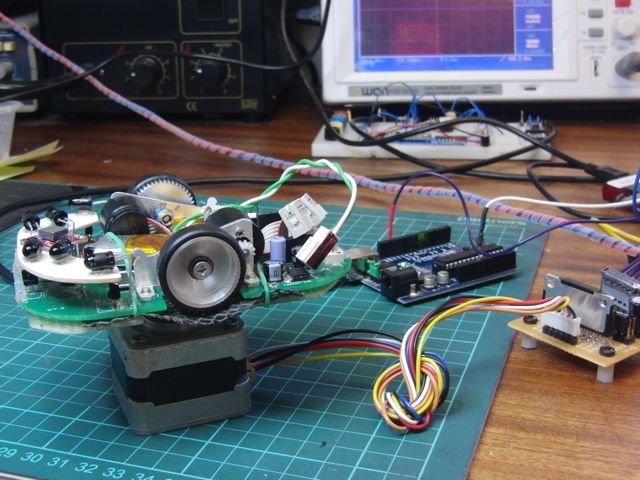
What I needed was some way of turning the mouse through a know angle or continuously at a known angular velocity. Like many micromouse builders, I started out with a stepper motor mouse so I have spare stepper motors and drivers available. I also have an Arduino clone which is a delight to use, making it very easy to write a quick program and have it do something.
I took an old, blank mouse chassis and mounted it on a Meccano wheel hub which, conveniently, fits perfectly on the stepper motor shaft.
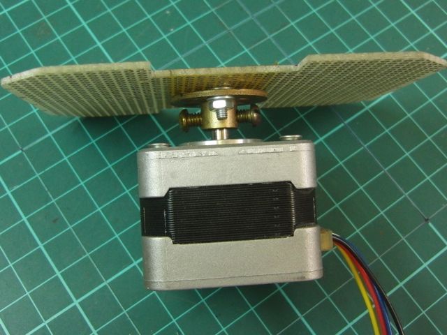
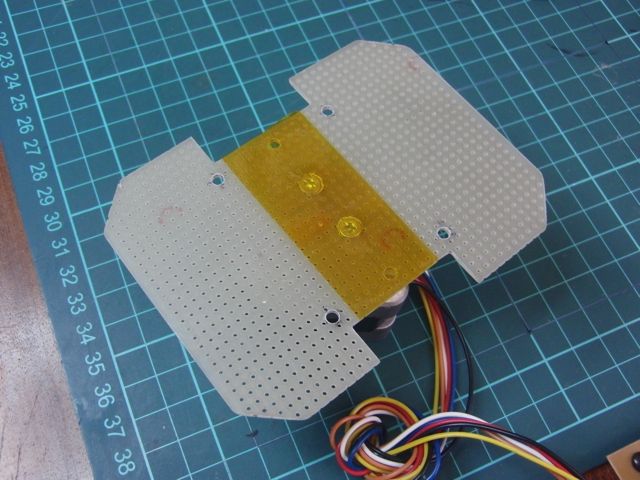
The mouse is held onto this with elastic bands. A small piece of non-slip mat under the mouse ensures that it is not likly to come flying off at high speed. Guess how I discovered you need that.
Now things are easy. First, program the Arduino to turn the motor exactly 360 degrees. I have a microstepping driver with 16x microstepping available. That means 3200 steps for a complete turn. The motor need only turn slowly but it should turn as smoothly as possible. The mouse and the stepper driver cannot communicate so I arranged for the mouse to take an average of the stationary gyro offset and then, every millisecond, it subtracts the ADC reading from the offset and adds the result to a variable. The mouse is integrating the gyro rate to get the turn angle. After a period of time long enough to ensure that a full turn has been done, it can send the recorded angle over the serial port. the value obtained is recorded in a spreadsheet and a further 9 trials performed to get an average value for the number of ADC counts corresponding to 360 degrees.
I oversample the gyro four times every millisecond and, for Decimus2, I end up with an average of 654555 for 360 degrees. Notice how these numbers get quite big quite quickly. The standard deviation for these results is only 2163 so I am fairly confident that the results are consistent and correct. Now, I have a basic calibration value of 1818 ADC counts per degree. Or, if you prefer, 1.818 ADC counts per degree per sec since the gyro is sampled every millisecond.
That value is all I actually need but I wanted to double check it and to find out what range of angular velocities I could measure. The ADXRS devices only specify their range in terms of a guaranteed minimum. Take the ADXRS610 configured as in the datasheet. AD claim it will indicate +/-300 degrees. But they give the sensitivity as 6mV/deg/sec. That implies that the output will only swing between 0.7V and 4.3V for that range of angular velocities. The device is perfectly capable of recording up to 400 deg/sec but AD want to be sure that all the various effects that can shift the bias point can never take it beyond the value that will guarantee a swing of +/- 300deg/sec.
Anyhow, now that the mouse is on the test platform, it is not hard to arrange to have it turn at a constant angular velocity under the control of the Arduino. All that is needed is a constant pulse stream at the correct frequency to turn the motor at the desired speed. The Arduino tone() function is pretty accurate and I monitored the frequency on the oscilloscope to check that the frequency was indeed what was desired. It is important to accelerate the motor up to speed as it probably won’t have enough torque to start straight up at top speed.
Once up to speed, the mouse records on second’s worth of rate data. This is the ADC reading, oversampled in the normal way. The average of those 1000 samples is reported after each run. For decimus 2, the results look line this:
| w (deg/s) | GyroRateRaw | Less Bias |
| 0 | 2025.436 | 0.000 |
| 360 | 2679.379 | 653.943 |
| 720 | 3333.653 | 1308.217 |
| 1080 | 3987.209 | 1961.773 |
When plotted on a chart, you get:
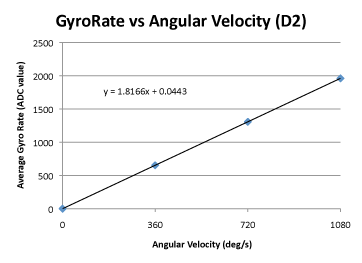
The results are wonderfully linear. The gyro (ADXRS610) has a 100k resistor placed in parallel with the feedback capacitor and can respond perfectly well to angular velocities of 1080 deg/sec. The slope of this graph gives the gyro sensitivity. The value of 1.817 ADC counts per deg per sec agrees very well with the result obtained from the 360 turn test so I am pretty happy. For completeness, 1.817 ADC counts is 2.22mV/deg/sec.
Now all I have to do is to get the mouse to turn that fast, under control of the gyro. How hard could that be?
Hi Peter,
I hope you don’t mind another question!
So far, I have been testing a gyro. Every millisecond I have the following:
diff = ADC_Result[GYRO] – GYRO_NULL_POINT;
if( ABS(diff) > 1)
gyroDir += diff;
It appears to work fine so far, but have you needed to do any filtering like the if statement here? I
am worried that it won’t pick up any slow rotation, like drifting while running down a long straight.
Thank you!
I also had the same question, could we please get an answer?
No, I have not filtered mine. Simply accumulate the rate information to get angle.
However, Galen is simply ignoring small changes. I do that to remove low level noise. It is not clear to me that it is the correct thing to do though.
Hi Peter,
Thank you for your answer!
May I ask how much low level noise you need to filter? Like I mentioned above, I’m worried about missing slow rotations, like a slight slippage while moving down a corridor.
It would be very nice to use the gyro to keep steering corrections to a minimum.
Thanks!
Well, I make no claim to be doing it correctly but…
When I read the gyro, I do so four times – all together – and add the four values together. This is averaging without the division. oversampling really. The gyro zero value is also obtained with oversampling. Then, when obtaining the rate, I ignore any rate values smaller than +/- 4. While this appears to work for me so far, it is on my list to investigate properly.