At the heart of a micromouse is usually a pair of position controllers. These maintain the mouse position for one of two kinds of movement – forward and rotation. Each can be configured independently. Like any position controller, the idea is to get a fast, stable response to changes in the demanded position…
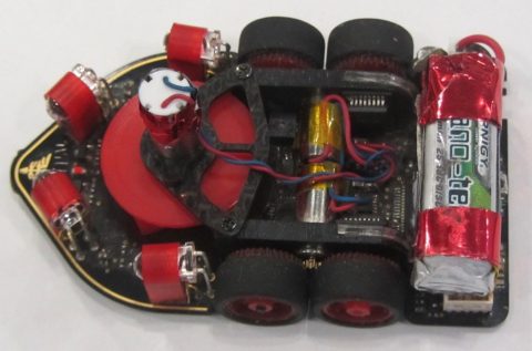
Position control by DC motor is a classic control engineering task. However, be absolutely clear about one thing – I am not a control engineer so, if this does not work for you, I am sorry but I can be of limited help. Here is an example of how you might design a common type of position controller. The example system is a simple metal disk attached directly to the output shaft of a Faulhaber 1717SR006 motor with attached 512 pulse encoder. The disk was chosen to present a load similar to that seen by each motor on a small micromouse. The motor is driven using the micromouse board through its motor driver and using the on-board mouse software. For experimenting with the technique, this lets me try several options without the risk of damage to the actual mouse or its motors in the event of everything getting badly out of shape. And, while experimenting with motor controllers, that is quite likely. I have no desire to watch my micromouse fly off the table – again. A future post will show another method and the working for an actual mouse.
The first step in any case is to characterise the system as described in the previous port here.
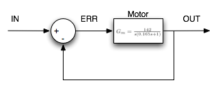
From the results, I obtain a transfer function for my test rig of:
![]()
So, the DC gain, Km, is 142 encoder counts/sec/pwm count and the time constant, Tm, is 0.165 seconds. All the tests were done with a supply voltage of 7.25 Volts. An odd value but that happens to be what the bench supply was set to. the PWM system has a range of +/-1024.
In practice, these constants means that, if I apply a PWM value of 200, I get (7.25*200/1024) = 1.416 Volts at the motor and it will turn at (200*142) = 28400 counts/sec = 3330 RPM. The data sheet for the motor tells me that the voltage constant for the motor is 2410 RPM/Volt which would mean I should see 3400 RPM. Close enough. The motor driver will have losses and the actual voltage at the motor will be less than calculated from the PWM value. This is a good validation of the accuracy of the measurement method. The time constant indicates that the motor will take about 3*0.165 = 0.5 seconds to get within 5% of the final speed and about 0.75 seconds to get within 1% of the final value. Now that is not very fast really. This will bee true for any applied voltage. With a higher voltage, the motor will spin faster but it will always take 0.75 seconds to get to 99% of its target speed.
Proportional Control
For the mouse, I use position control. This is done by comparing the output position with a set point. The error value is the difference between the two and is used to generate a PWM signal to make the motor move towards its set point. Clearly, if there is no error, there will be no PWM drive and the motor will not move. If the error signal is used as it is, we have a simple unity feedback system.
With the current position (OUT) at zero, we can apply a new set point of, say, 256. This generates a PWM drive of 256 and the motor will start to accelerate toward the new position. As it gets closer, the error decreases and the drive gets less. When the motor is at position 256, there will be no drive. However, by now, the motor is spinning and the inertia of the load makes it want to continue so it will overshoot. The error grows but in the opposite direction and eventually, the motor will slow to a halt and then reverse direction until it is heading once again to the set point. Where it will overshoot again. It should be clear that the system will oscillate about the set point. Losses in the system will cause it to eventually rest at the new set point but that could take a couple of seconds during which time the motor is spinning back and forth.
It might seem a good idea to increase the drive level a bit more to get the motor moving toward its set point faster in the hope it will settle down faster. The problem with this is that it will also pass through the set point faster and be even harder to stop. A DC motor position system like this is inherently stable and will always settle to the set point eventually but it clearly is not much good as a position controller.
PD controller
The fundamental problem here is that of slowing the motor down as it approaches the set point. What is needed is some kind of force acting in proportion to the speed at which the motor moves. While that would prevent the motor from moving to the set point as quickly as before, it would also help prevent the overshoot so that the motor could get within some acceptable error limit faster than it would with just proportional control. Since speed is the derivative of distance, this kind of controller s called a Proportional-Derivative (PD) controller.
The simplest way to implement such a controller, albeit not necessarily the best, is to keep track of the current error and the previous error and generate a drive signal based on both the error and the rate of change of the error. This is called the parallel method and, no doubt, proper control engineers will tell you it is not good. Not to worry, they have to deal with any number of complex systems. It works just fine here. In code, it looks like this:
errorOld = error;
error = setPos - currentPos;
PWM   = kP * error;
PWM  += kD * (error - errorOld);
Pretty simple really. The hard part is how to determine the value of the constants kP and kD. Searching around, you will come across lots of places that will try and tell you how to tune systems like this. They are mostly aimed at situations where you have a controller and you have a system but you don’t know the characteristics of either terribly well so that you have to then find a way to work out, often by trial and error, what values to use for the controller parameters. trust me, there is no fun in that and it is best avoided.
For this system, however, the characteristics are known. Only the time constant, Tm, and the DC gain, Km, are needed. First though, a bit about step responses.
Step Response
By examining the response of a system to a step change in input, it is possible to tell quite a lot about it. Conversely, if the nature of the step response is defined as part of the design, it is possible to create a system to satisfy those requirements. In this instance, like the mouse, we want the response to be quick and accurate. In practice that means, how soon can the system get within some specific tolerance band close to the set point. It is possible to design systems that move smartly up to the setpoint without overshooting but it is faster to allow a small overshoot and put up with the output being a little bit in error for a period of time.
The amount of overshoot is determined by the damping factor, ζ, pronounced ‘zeta’. A typical value for a slightly underdamped system with an overshoot of a couple of percent would be around 0.7. You can look up graphs and tables showing how ζ is related to overshoot. For now, I will just go with a value of 0.7 for ζ.
Having overshot, the system will take a certain amount of time to settle dowd. That time is tds and I will arbitrarily set it at 0.070 seconds. There is no point in making his number too small Whatever the control system, there are physical limits to what the system can achieve. Remember that the motor has a time constant of 0.165 seconds and so how can we arrange for it to get to within some small percentage of any step change in value in only 0.070 seconds. Well, that is what control systems are for.
The settling time and the damping factor between them are determined by the natural frequency, ωc, in radians per second. For this system, we have
![]()
We already have values for Km and Tm so:
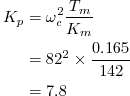
and
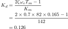
It is not very conveninent to use floating point so each constant can be scaled by 256 and the resulting output divided by 256 afterward. Also note that the derivative value is the derivative for one loop of the control system which, in this case is 0.001 seconds. To get it back to its value for one second, just multiply by 1000. All the variables here are longs (32 bit) since there will be overflows otherwise. Now the code looks like:
kP = 1997L;                    // 7.8*256
kD = 32256L;                   // 0.126*1000*256
errorOld = error;
error = setPos - currentPos;
PWM   = kP * error;
PWM  += kD * (error - errorOld);
PWM = (PWM + 128) / 256;       // scale back down and round off
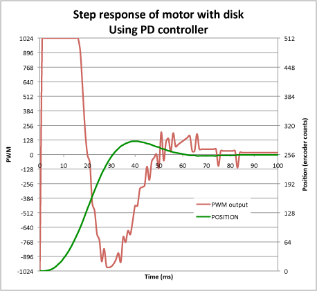
How well does that work? The code above was used with the motor and disk combination characterised at the start of this post. The motor was required to perform a 256 count step. That corresponds to half a rotation. During the more, the motor position and PWM output were recorded:
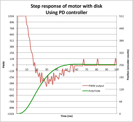
It is perfectly clear that the motor gets within 2% of its goal in under 50ms, exceeding the 70ms settling time requirement – a significant improvement on the unity gain feedback. There is also no appreciable oscillating of the output. In fact, this is a pretty stable system that could probably live with a little higher gain which would speed up the response at the expense of a little more oscillation around the set point. In practice, step sizes of only a couple of encoder counts are likely to be required of the system in any given interval. It should be more than capable of dealing with those. For example, a mouse having 50 counts per mm, might accelerate at 10m/s/s which is only 0.5 counts/ms/ms.
Notice the PWM line. First, the drive system saturates at maximum power for 10ms. If your batteries are not up to much, or if you have losses in the drive system, you might find that the supply voltage could drop dangerously during this period. At best, that means reduced drive and a slower system response. At worst, the processor voltage could drop low enough to reset the processor or at least cause a brown-out event. Be sure to check for these effects or you will have potentially serious problems.
Second, the required PWM is pretty erratic in places. This is, I believe, due to the discrete nature of the encoder feedback. Derivative control is sensitive to noise and the small jumps in encoder values – inevitable as they are discrete values – are amplified by the controller and cause possibly large changes in the PWM output. This is not very helpful but is a feature of this kind of controller. It can be eliminated but it may well not be worth the effort.
Just from curiosity, I doubled the gain, making kP = 15.6 and ran the test again:
You will see that the output manages to get to, and stay within, 12% of the set point in under 30ms. Note also that the first 20ms or so of the response are the same as they were before. After all, the motor drive is saturated and simply has nothing more to give.
Two things to worry about though from a performance point of view. First, notice that, as the motor gets up to maxumim speed and starts to close in on the target, the PWM drive is forced to go negative, almost saturating, in its efforts to slow the motro down in time to prevent excessive overshoot. This system is probably at its limit for this test. A higher drive voltage would help but we do not have one on the mouse.
The second observation is that no account is taken of the speed of the motor. in this test, the motor starts off stationary and finishes stationary. In a mouse, the motor may already be turning at some significant speed and some of the available PWM headroom is being used just to maintain that speed. Further attempts to accelerate or decelerate the mouse may run out of drive sonner than you would expect from a static test like this. It does occur to me, though, that braking is always easier as there will be additional headroom in the direction opposite to the current motion.
This turned out longer than expected so a second post will deal with an alternative control technique that is a bit better suited to the task.
.
I am about to get to the task of building my first micromuse, and reading your recent posts has helped me a lot. I just wanted to thank you for spending your time on publishing all this usefull information.
Saludos desde Argentina.
Hello Peter, I’m trying to do the same or similar (speed control of my robots motors). I understand what you did in the previous post, but not at all in this post. You speak about “natural frequency” wich seems to me a closed loop response, not a step response, but my knowledge about PID is very, very little, so I may be saying wrong things. The part where you calculate Kp and Kd is a mystery to me, can you tell me where those formulas are from? I spent several days digging internet looking for them but have not make into the goal. Is there a formula to calculate Ki also?
My goal is to control my motors speed. I have been looking for info on Ziegler-Nichols, Cohen-Coon, Skogestad, and others for how to determine the constants but I still do not understand how to. Most people uses software like MatLab but I will prefer to do like you, pen and paper (or excel at most). I will agree any ray of light in this “dark world” wich seems to be the PID tunning.
The calculations for Kp and Kd are just from examination of the transfer functions and the desired step response. Any decent controls tutorial or textbook should show these. If it were that easy though, there would be no need for any of the elaborate tuning methods you will have come across. The values calculated are a reasonable first approximation which should get things going at least.
I have not looked at an estimation for Ki. Matlab is, for me a misleading tool because there is no clear path to turning the Matlab solution into useable code. Matlab code generation is a nightmare.
For your robots, I would strongly suggest you skip the PID control and look at the next article about phase lead controllers. These are, in fact, a filtered PID controller but the calculations are more robust. I have found that I can simply do the drive train characterisation and plug the required values into my spreadsheet to get a perfectly acceptable controller first time round.
https://micromouseonline.com/2011/05/16/designing-a-phase-lead-controller/
Hello Peter, I’m trying to use PID to move every onecell but my loop in that function not stop why ?
Here my code :
void moveForward(int distance_pulse) {
// khoi tao toc do
float current_speed = 70;
float lsp;
float rsp;
int pos[NUM_MOTOR] = {0, 0};
//reset encoder
resetEn();
//reset angle
readDistance();
//reset P, I, D
//khoi tao vong lap dieu kien xung < xung mong muon
while (abs(posi[0]) < distance_pulse || abs(posi[1]) 100 || distance.right > 180) {
wall_error += 100 – distance.left;
}
if(distance.right > 110 || distance.left >170) {
wall_error += distance.right – 110;
}
if (distance.left > 180 && distance.right > 170) {
wall_error = 0;
}
if (distance.forward 150) lsp = 150;
if (rsp > 150) rsp = 150;
if (lsp < 0) lsp = 0;
if (rsp < 0) rsp = 0;
rmotor.drive(rsp + 1, 1);
lmotor.drive(lsp, 1);
//gan gia tri error previous cho error moi
Serial.print(posi[0]);
Serial.print("\t");
Serial.println(posi[1]);
delay(1);
}
delay(2);
rmotor.stop();
lmotor.stop();
//dua motor speed ve 0
}
It is really hard to know from a small code snippet.
However, the while loop terminating condition is the likely cause. The code fragment is actually a bit broken but try altering the condition so that it is only dependent upon the distance, nothing else.
So sorry for that messy code but distance you mean pulse count ?
Yes. If I have understood the code right.
try replacing this:
while (abs(posi[0]) < distance_pulse || abs(posi[1]) 100 || distance.right > 180)with this
while (abs(posi[0]) < distance_pulse )