On April 26th 2014, Birmingham City University was host to the 14th annual Minos event. The change of venue brought a number of advantages but otherwise, the weekend followed the usual format of talks and lectures on the Saturday and contest on the Sunday.
The Saturday brought a good mix of presentations from the attendees. Subjects covered many subjects of interest to all builders of small robots. The lineup went like this:
- Contest Feedback : Peter Harrison
- Our First Robot. Let’s reach for the moon : Jason Harrison
- Line Sensors, Motor Drivers and so Forth : Duncan Louttit
- This and That – a product review : Ken Hewitt
- Vision 2 – a proposed design : Rob Probin
- Creating Diagonal Paths for a Micromouse : Peter Harrison
- Building a competitive Line Follower : Chris Balmforth
- What stops you getting to first place? : Alan Dibley
- How would you do it? : Bernard Grabowski
- Data Logging in a Micromouse : Harjit Singh
- Building a Flexible Hexapod : Vadim Melnicuk
- Sunday Contest
Contest Feedback
Peter Harrison
This is a regular opportunity to get a look at some of the more interesting entries from micromouse contests in Taiwan, Japan and the USA. While the Micromouse Classic contest still has plenty of scope for stiff competition, there is a tendency to convergent design with many hardware platforms looking quite similar. Even so, in Taiwan, Lunghua University are developing a very economical micromouse to use in student projects. Green Ye, in the USA has another economical design for use by students at UCLA and there is, of course, the fabulous camera mouse by Shinichi Yamashita.
The line follower contest are a long way from that and in the past 12 months, the various line follower contest have been treated to a great variety of designs. Some highlights include a hovercraft, a helicopter and an omnidirectional follower.


Slides: contest-roundup-2013
Our First Robot. Let’s reach for the moon
Jason Harrison
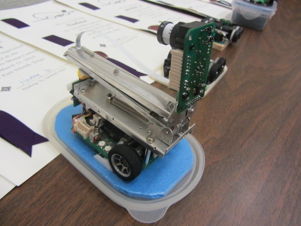
In the 2014 IET contest, a notable local entry was from Aston University. Jason Harrison and the rest of the team (Luke Prentice, Rob Hodgekins and Milan Salek) built their robot from scratch in a remarkably short space of time. As first time builders, they faced many challenges and their session was an honest and open appraisal of their build. As it turned out, their robot performed very well. After finding out what was going on behind the scenes, their success was all the more remarkable.
Slides: Reach-for-the-moon-Jason-Harrison.pptx
Line Sensors, Motor Drivers and so Forth
Duncan Louttit
Duncan also entered the IET contest earlier this year. In common with all the other contestants, he was obliged to use the drive train supplied for the contest. Unlike the other contestants, Duncan is no great fan of PWM for driving motors. He takes the view that a DC motor should be driven with DC. To that end, he used a DAC to provide a DC drive voltage and analogue electronics to control the motor speed. In his presentation, he described in some detail the operation of this analogue drive. One day, I should do a good comparison of DC motor drive methods. The analogue theme was also seen in his approach to the line follower sensors. Rather than take samples from each sensor and manipulate them in the processor, Duncan combines the signals with a simple difference amplifier and feeds a single ADC channel directly with the error term.
Duncan is also a dedicated user of Forth as a programming tool. All his robots make use of Forth and many of the advantages were described here. Attention was drawn to the ready availability of cost-effective Forth systems from MPE. In particular the ARM Cortex-Mx and MSP430 Lite Cross Compilers. these are free for non-commercial use. LINK
Slides: PREFLITE-Duncan-Louttit.ppt
This and That – a product review
Ken Hewitt
If there is anyone in the group who is keeping up with the latest gadgetry, it is going to be Ken Hewitt. Every year, he turns up with great news of recent toys essential equipment that we all need. This year, Ken introduced us to the impossibly small Hubsan Nano quadcopter. Around the same size and weight (12g) as a half-size micromouse, this is a fully functional stabilised flying machine. It just needs line sensors and the game is on. Arguably more useful for a robot builder is the growing range of MEMS inertial sensors. The MPU6050 is avery versatile 6-axis sensor that is less than 5mm square. So long as there are not unacceptable delays in the data, it looks very useful – even for micromouse. For a more retro feel to your projects, you might also want to consider a return to BASIC. For only $7.99, IV BASIC promises real programming on your iOS device. Looks interesting.
Slides: Ken Hewitt minos 2014.pptx
Vision 2 – a proposed design
Rob Probin
For some time, Rob Probin and Alan Henness have been working on a vision-based micromouse. Unlike MM-7a, mentioned above, the idea is to have real-time guidance based on information only from a forward pointing camera. Among the difficulties to be overcome are the relatively low frame rate and the available processing power and memory in the LPC2106 devices used on their robot, Vision 1. In the last couple of years, there have been huge changes in the nature of the available hardware. Notable among these it the ubiquitous Raspberry Pi. For very little money, it is possible to buy a computing device small enough to fit on a micromouse and yet having a 700 MHz ARMv6K processor with 256 MB RAM to play with. That alone would be a huge leap ahead – especially as the processing environment is Linux and there is a huge array of available tools. The icing on the cake though is the presence of a dedicate graphics processor on the chip which can do a lot of the heavy lifting now that driver support is more readily available. Add to that the high-resolution Raspberry Pi camera and you have a very powerful combination that really looks to be capable of getting the job done.
Slides: Vision2 v1_4f
Creating Diagonal Paths for a Micromouse
Peter Harrison
MAny beginners in micromouse focus on the question of ‘solving’ the maze. We often tell them that this is going to turn out to be the least of their worries and that they should leave it until later – once they have a working platform. I guess they are worried about how to calculate a path through the maze for their micromouse to follow. So long as the need is to find the shortest path and follow it to the goal, the problem is surprisingly simple. That is not what this presentation is about. Here, Peter Harrison considers the next step – how to turn a simple path made up of straights and in-place turns – into a smooth sequence of moves making use of the diagonals. This kind of path finding is essential for short run times. Curiously, it is not clear that a method for doing this has been published before. There are some examples in other mouse source code but hey are hard to unpick. Far better to write your own. The method described is relatively simple and makes use of a state machine to generate a diagonal path in one pass through either the maze data or a simple, orthogonal path description. Full details will appear in a future post on this site.
Slides: diagonal-pathfinding-ph
Building a competitive Line Follower
Chris Balmforth
Another contestant from the IET contest was Chris Balmforth. Like all the other contestants, he was constrained to use the same mechanical drive train. Unlike all the other contestants, his entry was smooth, reliable and much faster. Happy to share, Chris agreed to give away the benefit of the lessons he learned while developing this mouse. It is worth pointing out that the IET contest requires that contestants enter the same hardware platform in three events – line following, wall following and drag race. Drawing heavily on the example of the Pololu 3Pi robot, Chris constructed a device that performed very well in all events. If you are starting out or do not have great experience (and even if you do) there is much to be gleaned from this presentation.
Slides: Minos2014_line_follower-Chris-Balmforth.ppt
What stops you getting to first place?
Alan Dibley
In the first of two discussion-style sessions, Alan asked members of the audience to share their weaknesses. That is – what particular aspect of building small robots presents the greatest difficulty.
How would you do it?
Bernard Grabowski
Another experienced builder of small robots, Bernard works with local schools and develops robots that are flexible and good performers. Here, he invited the audience to join in tackling one particular aspect of building a line-following robot. The task is actually rather more difficult than it may appear at first sight. Designing the optimum sensor geometry is definitely not a well-understood problem and has no consistent solutions. The sensors designed to detect the turn indicators are especially difficult to get right. SInce Bernard did not have slides, I have reproduced here his summing up:
I entered the IET robotic triathlon and was faced with the prospect of producing a combined wall follower/line follower/drag racer in about 4 weeks.
In conjunction with Duncan Louttit I had previously produced a design for a similar robot which was made available to schools. To save time I used the schools mouse circuitry for the IET entry.
Problems arose due to the schools line follower rules variation where the competitors do not have to stop to get a lap time. There was no provision to detect the side markers in the schools mouse circuit. Even worse, I had not realised that reading the side markers reliably was not a trivial matter.
In my abortive attempts to read the start/stop markers I had concluded that:
* Reliable readings were not helped by a “wobbly” mouse due to poor PID motor control.
* Simply detecting the leading edge of the side markers was not going to work as even microscopic wobble could give multiple detections.
* False indications could be produced by track crossovers unless these too could be reliably detected.
I appealed to the MINOS attendees to share their techniques for overcoming these issues. Suggestions were made and are summarised below. I also realised after seeing photos of competitive line followers during Peter Harrison’s talk that the relative positions of the line sensors and the side marker sensors also needed to be considered. The successful followers tended to have the line sensors well ahead of the side marker sensors. Mine had all the sensors in line – the worst configuration apparently!
Summary of suggestions from the floor:* Using wheel odometry to ensure the robot travels clear of the side marker avoids multiple indications and allows a leading edge detection method to be used.
* Reading both the left and right hand marker sensors allows the detection of crossovers. For example if the leading edge of the right hand marker is detected and the left hand marker is not detected by the time the right trailing edge is reached it is not a crossover.
* Use two side marker sensors on each side instead of one, positioned perpendicularly to the side marker, spaced about 10mm apart. If both register a “hit” it must be a marker.
* Count the number of times the side marker is detected for a known distance after the first indication. Any count above a predetermined threshold must indicate a side marker.
* Use shift registers to process the output of the side marker sensors. Use logic to detect the presence or otherwise of the side marker.
I am grateful to all the contributors for their input and I promise my next line follower will stop at the right place at MINOS 2015.
Data Logging in a Micromouse
Harjit Singh
We were very fortunate, once again, to be able to welcome Harjit Singh to proceedings. Harjit lives near Seattle on the West coast of America. He was not able to visit in person but, thanks to the magic of Skype, he was able to deliver a very interesting talk about data logging. Plenty of people build perfectly good micromouse robots with no on-chip debugging and only LEDs and the simplest of serial communications to give feedback about what the mouse is doing. Now, on-chip debuggers are not much use when the mouse if rushing around at a couple of metres per second. Bluetooth is an alternative with data collection on a remote PC. Data rates, however can be slow and difficult to manage. Harjit has overcome this limitation by using serial flash memory devices. These are available in capacities of several MBytes and, while they can be slow to erase, are able to easily soak up several hundred bytes per millisecond.
Harjit’s approach is to log as much as he can. During the APEC 2014 contest, his mouse logged 2.7MB of data. All this is non-volatile and can be examined at leisure. As he says. If some incident occurs and the data was not logged, you will never know what happened. That said, managing that volume of log data is difficult so Harjit describes two essential aides. First, a variable format data record that allows the simultaneous logging of many disparate data types. Second, a dashboard application that can take the entire record and extract the various types into a flexible and comprehensive display on-screen. Several examples of specific benefits are given.
Slides: Minos-2014-Logging-Harjit-Singh.pptx
Building a Flexible Hexapod
Vadim Melnicuk
The world may not be short of hexapod robots but Vadim has put a lot of work into a sophisticated design. All the parts have been designed and fabricated by him. That alone would be hard enough but Vadim has also designed a flexible architecture where each leg can be semi-autonomous under the coordinating control of a central processor. Communication between sections is through a CAN bus of the kind commonly used in motor vehicles. In principle, a robot with this architecture could adapt to loss or damage of a limb and still carry on with its task. This degree of flexibility would be very useful for search and rescue, or EOD and mine clearance.
Poster: Hexapod_Poster-vadim-melnicuk
With the convenience of ready access to an 11×11 maze and line-follower tracks, Sunday was a relaxed affair with everyone making the most of the opportunity to get in plenty of practice and swapping of information and stories with the rest of the participants. It has occurred to me more than once that this part of the weekend is at least as valuable as any other part.
After a few hours though, it was time for an informal contest. Line following, wall-following and maze solving events were held. Timing was manual and accuracy questionable but never an issue in the end.
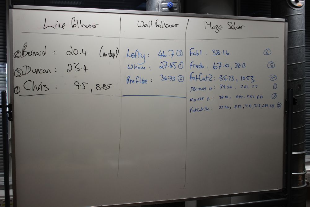
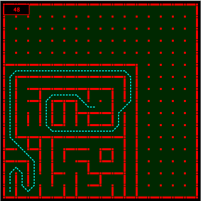
There is no picture of the line-follower track but the maze configuration was relatively short at 48 cells:
So – another Minos done! Our first at Birmingham City University and very nice it was too.
Our thanks to the attendees for making it all interesting and to the staff at BCU for making it all possible. We hope to be back for many more in the future.