JTAG is a common standard for communicating with modern electronic devices like FPGAs and microcontrollers. A JTAG connection will allow you to do in-circuit debugging in a bewildering variety of ways and will generally allow you to program your device. The standard, apparently, defines five connections for this purpose. Add in power and ground and you have a minimum of 7 connections needed to implement JTAG. The trick is getting them delivered to your board or device…
There are some standards in JTAG connections but, like standards everywhere, the nice thing is that there are so many to choose from. Since I am presently only interested in the use of the STM32 processor, which has an ARM cortex-M3 core, with Rowley Crossworks, I shall only describe what works for that. It should also work for other ARM processors and other development tools. However, you must check the actual pin allocations on your interface device and the target before getting all carried away with the soldering iron.
For ARM processors, the only real standard for JTAG connectors would appear to be the 20-pin DIL version:
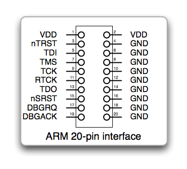 This is normally found on a target as a 20 pin 0.1” DIL box header for use with standard 0.05” ribbon cable and IDC connectors. It is a simple, robust connection that is easily implemented and far too big for a modest embedded application. I shall shortly want to be making a small device that is only 50mm x 40mm. The box header for this connection would require 30mm x 10mm – 15% of the board space. There appears to be another, slightly smaller connector in use – the 14-pin DIL:
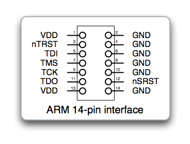 This is a distinct improvement and manages to save space by removing the optional connection. It is still quite bulky though so let’s have a look at the pins that are used. The first thing you notice is there are lots of ground pins. This is a good thing generally. On the 20-pin connector, it means that all the data lines have a ground line between them in the ribbon cable. That will help to ensure signal quality over what is a very high speed bus. However, if you were to use a 20-pin connection to a small adaptor placed very close to the board, you could compromise a little over the last inch or two. A 10-pin connector is described in several places but there seems to be no obvious consensus for what the pin connections should be. Consequently, I have simply used the same pinout as that chosen by Harjit Singh for his micromouse so that it will be a little simpler for us to share hardware and experience:
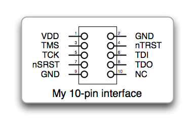 Harjit’s connector has the great merit that it can be plugged in the wrong way round with no ill-effects on the target. This is particularly handy since it will permit the use of a simple pin-header without the bulky cable shell and keying slot normally used. The cable headers still take up quite a lot of space but we are now down to only 18mm x 8mm of board space needed. Looking some more at this, there are still two surplus pins. An 8-pin version would still carry the necessary signals:
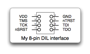 If this were plugged in the wrong way round, it could damage the target with the TDO signal possibly being held well above the target supply rail. Consequently, I would not recommend this without some kind of keying or other constraint to make sure it did not get connected in correctly.
Use with Crossworks
You may have noticed that one of the signals dropped in the smaller connector is RTCK. This signal can be used to dynamically controll the speed of the JTAG interface. In the target debuffer settings in Crossworks, you will want to turn off this option is the RTCK signal is not used. Look in the target properties window for an entry that says ‘Adaptive Clocking’. Set this to be ‘No’ if you are not using RTCK in your connector.
Rowley’s Crossworks does not use the nTRST signal for debugging. This line resets the JTAG hardware. Don’t leave it out of the connector in case you use some other software to talk to your target but be aware that Rowley do not make use of it.
Use with STM32
Be aware that the STM32 has internal pullups and pulldowns where needed on the JTAG lines. Another thoughtful provision by those nice people at ST. Other ARM processors are not as convenient and you should arrange to pull up or down the lines as appropriate:
- TMS, TDI, TDO, nSRST and nTRST should have pull-ups of 10k normally
- TCK, RTCK, DBGRQ and DBGACK should have a pull-down of 10k normally
Note that nSRST is the system reset and is normally connected to the RST line on the target processor. Usually, you should not connect the nTRST and nSRST lines. I don’t think it will make a difference for the STM32 and Crossworks but certainly will for a Segger JLINK.
As far as I can see, the STM32, and Cortex-M3 in general, do not use either the RTCK connections anyway.
Finally, here is the 10-pin connector implemented on a breadboarded STM32 target:

An alternative to the Olimex JTAG adaptor is the ST-LINK from STMicroelectronics
It is also possible to buy a ready-made adaptor to convert the standard 20 pin connector to the fine pitch ARM 10 pin connector. There is another one made my McGraigor Systems here.
“You should not connect the nTRST and nSRST lines normally”
Just to be clearer, I think what you could say is, “Normally, you should not connect the nTRST line to the nSRST line.”
I made that change if it makes things a little more clear.
Hi peteh,
Many thanks for sharing the setup.
I am getting an error : cannot set debug register. Any idea why this is happening?
I have the exact board and I connected the JTAG pins to the stamp board:
TRST->PB4
TDI->PA15
TMS->PA13
TCLK->PA14
RTCK->gnd
TDO->PB3
SRST->RST
On rowley, I set adaptive clocking to NO and divider to 10.
I take it you mean the same ET-STAMP STM32 board?
Are you using the Olimex JTAG programmer?
If so, there is an entry for it in the targets list for Crossworks. If not, can you share the exact details of your JTAG adaptor?
Hi Peteh,
Sorry for the long delay in my reply. I switched to Olimex STM32-P103 deve-board so I could continue working. Anyway I would love to get the ET-STAMP STM32 board working as well.
Yes, I am using Olimex ARM-USB-OCD debugger with the same setup and unfortunately, it is still not working in Crossworks with the same errors. The pin connections are same as before.
TRST->PB4
TDI->PA15
TMS->PA13
TCLK->PA14
RTCK->gnd
TDO->PB3
SRST->RST
There is an entry in the Crossworks as it worked with the P103 board from Olimex as well.
Thank you for your reply and sorry once again for missing your reply.
Hi Peteh,
I managed to resolved the issue. I didnt hold down the reset button to supposely bypass its original bootloader. It is working fine now.
Thank you.
I am glad it is working for you. It seems surprising that you would have to reset the chip though. unless, of course, your code uses the JTAG pins and changes their function I suppose.
Pingback: STLINK SWD for STM32 | Micromouseonline
I have found with the Olimex ARM-USB-OCD JTAG that different boards require different JTAG Clock Divisor settings to avoid the Rowley Crossworks “Cannot set debug register” error message.
On one board I could use a JTAG Clock Divisor of 32. On different board type I had to change it to 100 to get it working. These were both with STM32F103 MCUs with 8 MHz crystals. Therefore, I recommend trying some higher values if a particular board isn’t working.
To change the JTAG settings in Crossworks 2.1, open the “Targets” window from the Target menu, then right click on “Olimex ARM-USB-OCD” and select properties.
I’m new to JTAG (got out of 17 years of writing computer games in 2002) writing in 100% assembly language. I have a target for the 8-pin DOI connecter. Please, indulge me with the kit required for the target. If you make it, I will buy from you. If not, a recommendation. I need an adapter but have sourced one so I can change pins (if required). With many thanks.