Simpler is often a good thing. For the new mouse, I wanted to make the sensor arrangement as simple as possible. One way is to drive the emitters from the battery supply…
In the past, I have always driven the sensor emitters from a regulated voltage. The main reason is that the brightness of the emitters will not change as the battery voltage drops during a run. A down side is that you will be generating fairly large pulses on the regulated logic supply and this is a potential source of noise. Looking at pictures of mice, it was apparent that Kato’s Tetra and Bee have the sensor emitters connected directly to the battery supply. On the face of it, this is not a good idea since battery vopltage can vary quite a lot while the mouse is running around. Nonetheless, it seems to work well enough for him so how can that be?
A simple test rig has a sensor connected to an Arduino since these are wonderfully flexible and easy to use for this kind of experiment. The detector is connected in the usual way but the emitter has its anode connected to the bench supply. Now it is possible to set up a wall at a fixed distance and measure the output from the detector with various different supply voltages. What we hope for here is a linear relationship between the supply voltage and the sensor reading. If that is the case, simple scaling arithmetic will allow us to measure the supply voltage and calculate a correction for the sensor reading to make it independent of the supply. If the result is non-linear, then life gets more difficult and correcting for the supply voltage is tricky. Here are the results form a quick experiment:
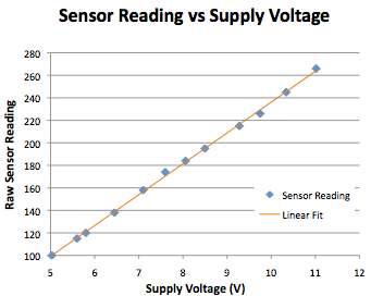
The results are not perfect because the experiment was cobbled together on the desk with whatever came to hand and there was a fair bit of noise. But there is a clear linear relationship between supply voltage and sensor reading. This is just what I would hope for. For the new mouse, it mean I can completely eliminate a voltage regulator whose only job would have been to provide a stable supply for the emitters.
Cool. The wonders of digital signal processing. I wonder if you can put a low pass filter between the battery/power supply and the anodes of the emitters to isolate motor noise from the emitter.
I would think a simple inductor/capacitor filter would do the trick. A pi filter now I think about it.
This has also made me realise something else fairly obvious. Calibrating for different walls should be a simple scaling so, once the shape for a given sensor has been determined, future calibration should be easier.
Unless of course you just use the raw values as an indicator of distance rather than try to calculate the actual distance.
Hello.
I don’t use the variable emitting. I drive sensor emitters with constant current by the bipolar transistor. 2SC3325 have a good hFE linearity, therefore the current isn’t influenced by the change of voltage. I set Ibe=0.5mA, so Ice=85mA=LEDs current.
This method is weak to heat. However, because the emitting time is very short, the generation of heat can be disregarded.
Ah – I really had not thought of that. I tend always to thing of transistors as simple switches but I had wondered why you had not used a FET there.
Having done some more sums on the scaling, it turns out not to be as reliable as I had hoped.
Thanks for the information.
Hi!
My sensor circuit is as below.
                              GND
                               -
                              ---
                               |
                              .-.
                              | |
                              | |1K               VCC (5V)
                              '-'                   ---
                               |           Detector  |
                    ADCx ------o-------------->|-----o
                                                     |
                                                    .-.
                                                    | |
                                                    | |10R
                                                    '-'
                                   |                |
                   PORTx ----------| >O-------|<-----o
                                   |/       IR LED
                               1/7 ULN2003
I used each inverter gate of the ULN2003 for each IR LED with a 10 ohms resistor separately. I’m not professional in electronics (a beginner for a few years). The algorithm for reading the sensors is:
1- Set PORTx ON
2- Waite 200 us
3- Read ADCx
4- Set PORTx OFF
5- Do 1-4 for all sensors
The result was low effect of the environment light condition on the sensors. I tested it in the outdoor (a sunny day), in a room with dark curtains and in a room at night with a fluorescent lamp. The adc difference was very low in the same distance conditions.
Hello. For left/right wall sensing of my 40 seconds mouse I use this schematic. Vb is dimensioned somewhat lower than below because of the leftLED en rightLED are switched in series. A single LED may be dimensioned
reduce V_PORTx (5V) such as 4 volts to Vb with divider R1,R2
Vbe is 0.6 volts for silicon. V_R3 sinks to 3.4 volts when PORTx is high and Vb is 4 volts.
With Vforward_LED beiing 1 volt, Vbat may reduce worst case to 4.4 volt otherwise the transistor saturates.
I Led is 3.4/R3. R1 and R2 should be scaled such that Ib is much smaller than I bleeder R1, R2.
A speedup C may be paralleled to R1.