So, lets assume you have a pair of suitable stepper motors for your micromouse. I have used the RS 440-420 steppers. these are a Nema17 size motors rated at 5V, 500mA drive.
The data sheet shows a winding resistance of 10 Ohm, inductance 6 mH and a holding torque of 70 mNm.
These will directly drive a wheel of outside diameter 50mm. Since the motor is a 200 step design, a single step will be 3.14*D/200 = 0.785 mm. However, I will drive it with a half stepping sequence giving me 400 steps per revolution with each step being about 0.39mm. the half-stepping sequence gives a smoother response and better performance at speed. The exact distance on the ground is not worth calculating up front. It is better to calibrate with your mouse by running, say, 5000 step (about 2m), measure the distance actually travelled and divide by 5000. For the micromouse, all distances are based on cells and steps. For the calculations below, I will assume a single cells is 450 steps long.
Driving Electronics
The drive electronics will be provided by an Allegro SLA7024 IC. This chip can drive a single motor in either unipolar or bipolar mode with chopper controlled current limiting. What this means in practice is that you provide as high a voltage as you can afford to carry in terms of batteries. The maximum current through the motor is limited by the driver and is easily set by a single potentiometer. The best performance from stepper comes from driving them in this way. A micromouse might carry 12 NiMH cells giving a nominal 14 Volts or so. Directly applying this to the 5V rated stepper will over heat it and reduce performance fairly quickly. A typical circuit for this chip is shown below.
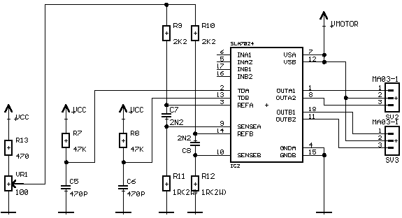
You can check the data sheet here ![]() SLA7024. One annoyance of this chip is that the designers seem to have taken delight in making it hard to physically wire up. The lead spacings are inconvenient and the pin arrangements do not lend themselves to a neat circuit layout. however, it does its job very well and is popular for this application.
SLA7024. One annoyance of this chip is that the designers seem to have taken delight in making it hard to physically wire up. The lead spacings are inconvenient and the pin arrangements do not lend themselves to a neat circuit layout. however, it does its job very well and is popular for this application.
If you don’t want the expense or complication of the specialist chip, you could use the simpler and cheaper UCN5804B stepper driver. This takes step and direction pulses and is much more convenient to use. However, if you are to run from a high battery voltage you will need a resistor in series with the windings to limit the motor current. Say you have a 14 Volt supply for these motors. The current limiting resistor can be placed in the common power supply and would need to be about 15 Ohm. With a current of 500 mA, the power dissipated in this resistor would be 3.75 Watts so you want at least a 5W rated resistor. This should, ideally, not be a wound type (the common one) at the inductance of the resistor may limit the start-up current in the motor. Now, not only is a suitable resistor a little hard to find, bulky and hot to the touch, you are wasting nearly two thirds of the energy in your batteries keeping the room warm. Compromises ever compromises.
Check out the data sheet to see just how easy the 5804 is to use ![]() UCN5804B.
UCN5804B.
Sequencing
If you use the 7024, you will need to provide a suitable set of signals at the inputs to the chip that will turn on and off the coils of the motor in the correct sequence. Check the data sheet for the appropriate sequence. Each motor needs one chip and each chip needs four signals. Thus you have a single port being used to control the two motors. The direction of the motor depends upon the order the coils are excited so by stepping up or down a table of values in the microprocessor, you can get full control. A bit of twiddling with the upper and lower four bits of data at the port gives independent control.
If you would rather not do this, you can use a sequencing chip like the L297. It takes step, direction and full/half signals and does all the sequencing for you. This is very convenient as your motor driver routine only has to worry about generating a single pulse on a single pin. The L297 works at normal logic levels and lives in a 20 pin DIL package.
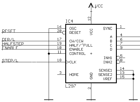
There are other functions in this chip which are not used in this application.
You can have a look at the data sheet ![]() L297.
L297.
The 5804 driver also needs step and direction signals and is very easy to use.
Speed Control
You can’t just bang away at stepper motors and expect them to do things. Steppers have a maximum torque at low speeds. the torque falls off quite dramatically with increasing speed. A high drive voltage helps to maintain the torque at higher speeds.
Because the motor is used in an open-loop configuration, you must, at all costs, avoid the motor stalling or missing a step. The key is a suitable acceleration and velocity profile.
At low speeds with the drive electronics shown, the motor might provide a torque of only about 50 mNm. That is about 2 N at the wheel rim, per motor. This is enough to accelerate a 1 kg mouse at about 4m/s/s or 0.4g. Now, 1m/s/s for our mouse is around 2500 steps/s/s.
The available torque will decrease quite rapidly with speed and so will our ability to accelerate and decelerate. Consequently, we are unlikely to see accelerations of 4 m/s/s in practice.
For calculations, work in steps. All the events in the control of a stepper occur at intervals of one step of the motor. As the motor changed speed, the time between steps changes. This is quite different from the way you would drive a DC motor where fixed time intervals are used.
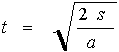
To drive the motor, you need to emit pulses at decreasing intervals until you have reached some maximum rate and then increase the intervals again until you come to a halt. The intervals can be calculated from the acceleration and the step number by rearranging a bit of the common equations of motion.

s is the distance travelled, here in steps, a is the acceleration, in steps/s/s and t is the elapsed time, in seconds.
Rearrange this to give
Now we use a program or your favourite spreadsheet to generate a table of values. The elapsed time is not much use to us so we calculate the time difference between successive steps to get a table that will look something like this:
| step | t | timer (s) | timer (us) | pulse rate |
| 0 | 0.00000 | 0.0000 | 0 | |
| 1 | 0.02828 | 0.0283 | 28284 | 35 |
| 2 | 0.04000 | 0.0117 | 11716 | 85 |
| 3 | 0.04899 | 0.0090 | 8990 | 111 |
| 4 | 0.05657 | 0.0076 | 7579 | 132 |
| 5 | 0.06325 | 0.0067 | 6677 | 150 |
| 6 | 0.06928 | 0.0060 | 6036 | 166 |
| 7 | 0.07483 | 0.0056 | 5551 | 180 |
| 8 | 0.08000 | 0.0052 | 5167 | 194 |
| 9 | 0.08485 | 0.0049 | 4853 | 206 |
| 10 | 0.08944 | 0.0046 | 4590 | 218 |
| 11 | 0.09381 | 0.0044 | 4366 | 229 |
| 12 | 0.09798 | 0.0042 | 4171 | 240 |
| 13 | 0.10198 | 0.0040 | 4001 | 250 |
| 14 | 0.10583 | 0.0038 | 3850 | 260 |
| 15 | 0.10954 | 0.0037 | 3714 | 269 |
| 16 | 0.11314 | 0.0036 | 3593 | 278 |
| 17 | 0.11662 | 0.0035 | 3482 | 287 |
| 18 | 0.12000 | 0.0034 | 3381 | 296 |
| 19 | 0.12329 | 0.0033 | 3288 | 304 |
| 20 | 0.12649 | 0.0032 | 3203 | 312 |
| 21 | 0.12961 | 0.0031 | 3124 | 320 |
| 22 | 0.13266 | 0.0031 | 3050 | 328 |
| 23 | 0.13565 | 0.0030 | 2982 | 335 |
| 24 | 0.13856 | 0.0029 | 2917 | 343 |
| 25 | 0.14142 | 0.0029 | 2857 | 350 |
| 26 | 0.14422 | 0.0028 | 2801 | 357 |
| 27 | 0.14697 | 0.0027 | 2747 | 364 |
| 28 | 0.14967 | 0.0027 | 2697 | 371 |
| 29 | 0.15232 | 0.0026 | 2649 | 377 |
| 30 | 0.15492 | 0.0026 | 2604 | 384 |
| 31 | 0.15748 | 0.0026 | 2561 | 390 |
The column that you would use in your code is the fourth one which shows the time between pulses needed to control the processor’s timer. This example assumes that you have a 1MHz clock for the timer. The actual table may have as many entries as you like although beyond about 500, the numbers are beginning to differ only by a couple each time and so the granularity of your timer makes it not worth getting too carried away. With the figures shown above, your motor will be stepping at about 1500 steps per second. Each motor will be doing this so your processor will be handling 3000 interrupts per second. Be sure to keep the code for the interrupt routines small and efficient. You should also try to be sure that there are no interrupts with a higher priority than the stepper driver. Once they are up to speed, a missed pulse or two will send them out of synchronisation and the motor will stall. The usual result is the mouse doing a rapid, unexpected turn into a wall. Guess how I know that? At 1500 steps per second, our example mouse will be doing about 580 mm/s or a little more than 3 cells per second.
Software
Actually driving the motor is now fairly straightforward depending upon the resources available in your chosen processor. If you only have one timer on your processor, you are a bit limited. However, even if this is an eight bit timer, it is possible to run two motors independently. To do the job well, you will need a 16 bit timer which can be clocked at 1 MHz or faster. The simplest option, available on pretty well any processor, will be a single (16 bit) timer that can be programmed to give a single interrupt at a fixed frequency. A better alternative is to have two such timers that can be made to generate separate interrupts as the time out. Commonly available on most processors is a timer with some kind of output compare. the output compare allows the timer to run continuously. A register (one per channel) holds a value that is compared continually with the counter value. When they match an interrupt is generated. Many such counters also allow the automatic twiddling of an external bit on a port at the same time. From a programming point of view the two timer and the output compare method are similar and will be dealt with as one.
Single timer, single interrupt
Suppose you have a single timer. If it can be set to generate interrupts at some suitably high rate – say 5,000 per second – you can implement a version of direct digital synthesis to create a stream of events at any frequency up to the interrupt rate. In practice, you should only expect to be able to get to a fraction of the timer interrupt rate to avoid excessive jitter.
The trick here is to use a phase accumulator. This is a 16 bit value to which is added a constant at each interrupt. The result is allowed to overflow but we detect the presence of the overflow and use it to trigger our secondary event. For example, we start out with the phase accumulator at zero and add the value 5466 to it at each interrupt. After 12 interrupts, the accumulator overflows while changing from 60126 to 56 and we can send a pulse to the motor. After a further 12 interrupts, the accumulator once again overflows and we send another pulse. In this way, we get a motor pulse at 1/12 of the interrupt rate – about 417 pulses per second in this case.
The value for the constant, P, is readily calculated. Let FT be the timer interrupt frequency and FE be the desired event frequency, the accumulator is 16 bit so we have a further constant of 65536 to give:
P = 65536*FE/FT
P = 65535*417/5000
P = 5465
This is quite easy to calculate, especially if you do the multiplication first (as you should). There will always be some jitter in this arrangement. The higher your event frequency, the worse it will be. Increasing the interrupt rate may mean that you take up all your time processing interrupts. To drive two motors, use two phase accumulators and two event handlers. The data for the acceleration tables will need a little more care in generation than that shown above but is not impossible. Alternatively, you could have a third accumulator generating events at a lower rate of, say, 100 Hz and implement a more traditional motor control loop that operates in fixed time intervals. New motor velocities and steering corrections can be calculated at those rates rather than at each motor step. Now you can have very tight, fast events to put steps out to the motors. Remember to be sure that any changes to the values of the motor constants are atomic in as much as you must ensure that a value can not be used half way through a change made elsewhere. Remember also that you will have only 1/5000 second to do all this unless you implement a system of flags that allows the low frequency event handler to run asynchronously. You should not let the motor step event handler run asynchronously as it is important that the timing of the pulses is accurate.
One timer with output compare
Your chosen processor is very likely to have this option available to it in some form or another. The 16 bit timer counter free runs at some frequency chosen by you. For the sake of simplicity, we will assume it increments at a rate of 1 MHz. A higher frequency allows better control at high speed, a lower frequency gives the possibility of running the motor at lower speeds. Really low speeds are not so useful so go for a high rate if you can.
Each channel will have a register which can take a 16 bit value. as the timer counts through this value an interrupt is generated. Your code then steps the motor and fetches a new value for the compare register. The cunning part of this is that the new value is added to the old value because we are dealing in time intervals rather than absolute times. Thus, the next interval must occur after so many counts. You don’t have to worry about overflow because both the timer and the compare register will be affected in the same way.
To accelerate the motor, just get the next value up from the acceleration table. Deceleration is a matter of getting the next value down. Be sure not to pass the bounds of the table and pick up rubbish. The table itself is conveniently held in flash/program memory.
Now we can describe the speed of the mouse in a particularly convenient way. We don’t really care what the actual speed, in m/s, is. Instead, speed tells us how far up the table we are. A very useful benefit being that we always know exactly how many steps are needed to come to a halt.
Here is some sample code from a stepper application. It is written in C for the AVR processor:
// interrupt handler for one output compare channel interrupt [TIM1_COMPA]
void timer1_compa_isr(void) {
  long remaining;
  if (stepper_enabled) {    // a global flag can disable the steppers
    PORTC.1 = 1;            // get the pulse done early to avoid jitter
    delay_us(10);           // it does not need to be long. The start of
    PORTC.1 = 0;            // the pulse could be automatic if you want
    stepper_pos++;
    remaining = abs(stepper_target - stepper_pos);
    if (remaining > speed)  // be sure there is time to stop
      speed++;
    else
      speed--;
    if (speed > speed_max)  // not too fast
      speed = speed_max;
    if (speed < 0)          // definitely not too slow
      speed = 0;
    OCR1A = OCR1A + timer_values[speed];
  }
}
Each motor has a target distance to cover. You will see that there is no special need to see if we are past half way - only that we have room to stop.
The motors can be controlled independently or as a locked pair. Steering corrections can be fed in as changes in the speed of each wheel. Special movements like integrated turns can have their own acceleration tables.
A summary of this page is available as a powerpoint presentation ![]()
A simple spreadsheet for calculating the timer values is also available here ![]() .
.
I’m feel interested in this topic now, i’m making 1 micromouse with language C and codeversion the function is trace the shortest way in a maxtric (in stock) http://micromouse.cs.rhul.ac.uk/mtech/rules_main.shtml but, I have a lot of difficulty in programing So, i’m want to consult your code thank so much!!!