Micromouse book
Categories
Recent Comments
Meta
Popular Posts
- Simple ADC use on the STM32 (3,934)
- STM32 Arm-Cortex bootloader (2,657)
- STM32 USART basics (2,533)
- All Japan Micromouse 2011 – finals (1,970)
- STM32F4 – the first taste of speed (1,615)
- Micromouse Book (1,532)
- Nokia 3410 LCD on the STM32 (1,264)
- CodeSourcery GNU Toolchain for the ARM on a Mac (1,097)
- Bit Banding in the STM32 (971)
- ARM STM32 JTAG (921)
Blogroll
-
Upcoming Events
-
Feb6Mon
-
Apr14Sat
-
Tag Archives: robot
Bob’s second outing
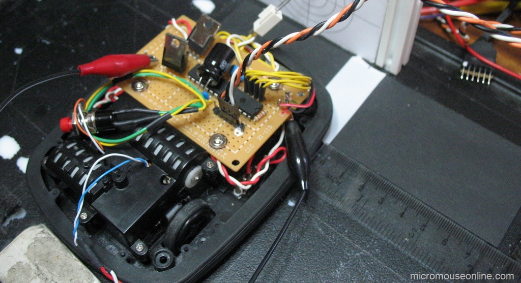
Bob has had a bit of minor surgery. I replaced the Darlington transistor motor driver with a L293D chip. Thing is, I forgot that the 293 has relatively large losses so Bob was much slower…
The idea was that the 293 would allow the motors to brake harder. With one side of the bridge permanently grounded, the motors would be actively driven or regeneratively braked. That worked fine but there simply was not enough voltage to get the motors up to any useful speed in the first place. After a poke about in the battery collection I found a LiPo 2-cell pack that would just fit in the battery compartment. I think the capacity is about 600mAh so it should be good for a couple of hours running.
The increase in speed was surprising and Bob nearly shot off the test track before I could catch it. However, when the speed is reduced to a level where it can reliably negotiate turns, I think I am no better off. The video shows that it still takes nearly 10 seconds to get around my little test track. I was hoping for more like 5 seconds but it just can’t turn hard enough when it encounters a bend to prevent the sensors losing the track altogether. I know the design is fundamentally flawed but I expected more. Next I shall try allowing Bob to control the motor direction as well as speed but I think I am wasting my time with it. There is supposed to be a nice PD controller in there but that too may be a waste of time.
Line Follower First run
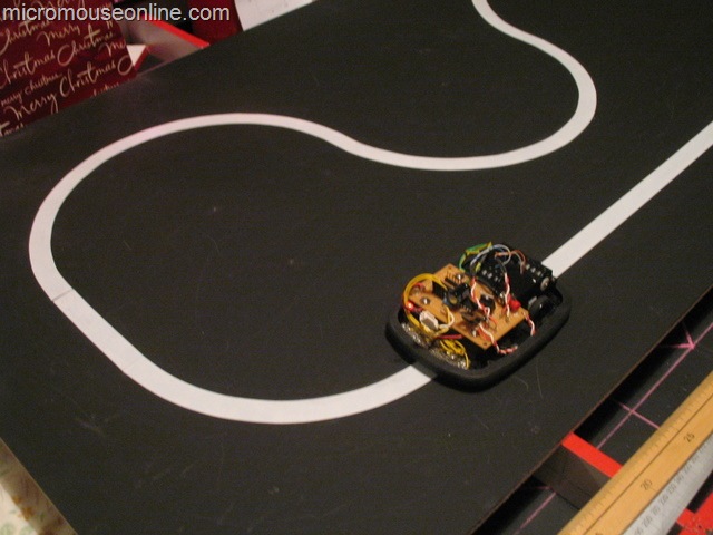
All the bits are together and the processor code tested. Bob should know when he is on track and how far out he is when he is off track. Time to get him running on the test track…
For this first run, the control was kept very simple. If the position error is positive, Bob needs to turn right. If it is negative, he needs to turn left. Turning is accomplished by removing power from the appropriate motor.
Well, that isn’t too impressive is it. Not that I expected much better at this stage. A couple of things worry me a bit though. The amount of wobble on the straights indicate that there is a lot of inertia and plenty of overshooting. The control loop is running at about 200 Hz and the frequency of overshoot is a couple of hertz. When I put Bob together, I though that having the wheels at the rear and the sensors way out in front would be a good thing. However, the batteries are well ahead of the wheels as well and have quite a bot of mass. The other thing is that, in the turns, the robot is only just turning fast enough to keep up with the turn even though one motor is off most of the time. Apart from the expected oscillations, this may also be due to the fact that the motor is driven from single transistor so there is little braking available. Once the PWM is turned off, the motor can freewheel so turning is not as sharp as it would be if the motor were braked. It may be necessary to replace the motor driver with a bridge to get better control. Finally, it is much noisier than I anticipated. Not serious in terms of performance but it wakes up the dog and, trust me, it is better to let this particular sleeping dog lie.
Line Follower Sensors Setup
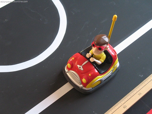
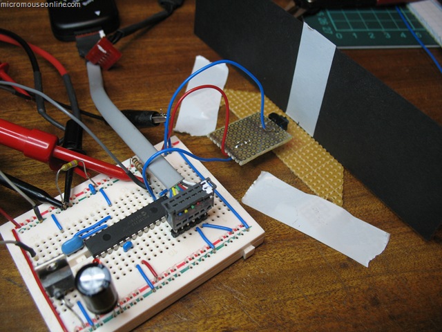
With the sensors installed and the robot pretty well complete, it is time to see if they can actually do the job they were designed for. the idea is that the line of sensors will be able to measure the robots offset from the centre of the line over as wide a range as possible.
In a previous post, I described how the error could be determined very conveniently by looking at the difference in reading between two sensors. This is very true and perfectly valid for the case where there are three sensors. Or even two. However, I put five on Bob and wanted to get as much of a displacement as possible. After messing with the simple difference technique for a bit I decided to get on and do the job ‘properly’. Well, as properly as I could think of today at any rate.
Bob has five sensors arranged at fixed intervals of 0.5 inch. This spacing is determined mostly by the fact that the sensors are mounted on 0.1" pitch perfboard. The fixed spacing turns out to be important and very convenient. A typical set of sensor readings look like this:
| Sensor | 0 | 1 | 2 | 3 | 4 |
| Reading | 127 | 124 | 9 | 45 | 125 |
the sensors are numbered from left to right from the driver’s point of view. Each reading has been normalised to a maximum value of 127 representing the black background so the low values are sensors that can ‘see’ the white line. It should be apparent that the robot is off centre to the left by some small amount as sensor 3 can see the line but not as well as sensor 2. Usually only two sensors can see the line at once. The spacing is such that, as soon as sensor three stops seeing the line, sensor 1 starts to see it. A slightly closer spacing would be better for the technique I am describing. I think a sensor spacing equal to the line width would be best.
So, we are interested in the response of three sensors. The one with the lowest reading and the sensor either side of that. We can plot the readings on a graph and try to fit a curve to the three we are interested in. Something like this:
The curve is a quadratic and you can see that the turning point – the minimum value – is in between sensors 2 and 3. It is closer to sensor 2 as you might expect. Without drawing lots of examples, it should also be apparent that the turning point will move toward sensor 3 as the reading on that sensor gets smaller and that on sensor 2 gets bigger. In fact, that turning point allows us to interpolate the actual centre of the line quite accurately as long as the sensor spacing is regular and appropriate. On BOB they are a bit far apart but it still works out quite well.
How can we find the turning point? the curve is a quadratic and we have three points that lie on it. thus the equation can be solved using simultaneous equations. Remember those? A technique for solving these things is to calculate differences. Again, I won’t detail the entire process but just give the result.
We have three sensor readings s1, s2 and s3 corresponding to the position of three sensors at positions x1, x2, x3. If we take the distance between the sensors to be a single unit, the position of the turning point, relative to s2 is:

Only the division need cause any problems for the code and I am using C so I can let the compiler deal with that. To help with the division and to ensure there are no overflows or underflows, it is convenient to perform the first part and then pre-scale it by 256 before doing the division. The result will be a number between -128 and +128 representing the offset of the turning point from the middle of the three sensor readings.
To test out the theory on Bob, I made up a rough test rig which would allow me to move a white line under the sensors in increments of 5mm and have the robot calculate its offset from centre. The test rig picture is at the top of this page. Here are a typical set of results:
Not perfect but they seem to do the job. The offset can be calculated over the full range of +/- 25mm from the centre. The results seem monotonic and fit a straight line quite well. Better spacing should improve this a bit but I shall leave them as they are for now. The way the ends of the range are dealt with could be improved since it should be possible to get good results out as far as +/- 40mm with this technique. Time is short however, so I will go with this for now
Line Follower Test Track
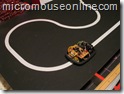
You can’t build a line follower without a test track to run it on. The proposed UK rules for this competition specify the track to be on a 300mm grid with fixed turn radii of 150mm. Well, I don’t have room for that and I don’t want to make tiles either so a little lateral thinking is called for…
What I do have room for is a sheet of MDF measuring 1220mm by 610mm. This is a standard size and should cost only a few pounds from the local DIY store. I bought a piece 6mm thick. It will be less stable than it might be and will curve towards the painted side but it is light and will do for my purposes. If the board were divided into six tiles, I could only make the simplest of tracks. However, one of the most important parts of the rules is the specification of the turn radius at 150mm. My line follower is quite small at 100mm wide and, unlike some of the South East Asian followers would be happy to run on tracks with only 60mm or so clearance to either side. After a bit of doodling, I decided I could fit this track into my piece of MDF:
View the PDF here. All the turn radii are 150mm and the length of the straights is whatever will fit. I am not using the turn markers and there is no odometry on the robot. A space of 100mm around the edge should be plenty one (if) I get it under control.
Ordinary matt black emulsion is used as the background of the track. This does not cover too well and MDF is pretty absorbent so three coats were needed and the surface has raised from the moisture. This pant will not be very durable but it is cheap and easy to use. The brushes wash out under warm water without any need for detergents and there are no noxious fumes. Proper blackboard paint would have been better but is quite unpleasant to use.
The centres of the turns and ends of the straights are marked out in pencil. An ordinary pair of compasses with a pencil in them can be used to mark out the turns at the 150mm radius. Lay down some 19mm white PVC electrical tape along the straights, taking care to place it centrally on the pencilled lines. Now you can take the compasses and set them to draw the inside edge of the turns. This will give you an edge to lay the tape against. Only the inside edge is needed.
Lay the tape by stretching it off the roll, smoothing down as you go. It should be quite easy to make it follow the turn. The whole job took about 20 minutes. Take your time and get it right as lifting the tape may well damage the paint surface. Once finished, mine looked like this:
Line follower sensor experiments
The simplest arrangement for a line follower is probably two sensors with digital outputs. As long as one can see the line and the other can see the background, the controller is happy otherwise it must turn left or right as appropriate. I was after something a bit more sophisticated for Bob the Line follower…
The first task it to examine the behaviour of a single sensor. To this end, a version of the Bob controller was made up on a breadboard and a single TCRT5000 sensor attached to a remote board. Black card has a white stripe added in the same way as the track. That is a single layer of cheap, 19mm white PVC tape. With the card mounted vertically, the sensor can be placed at varying distanced from the vertical track. A piece of perfboard taped to the desk lets me measure the distance between the sensor and the track as well as the lateral displacement. In this way a series of measurements can be taken as the sensor is moved across the track at different distances. All the room lighting is fluorescent with negligible IR content. The emitter is supplied from 5V through a 220 Ohm current limiting resistor. The phototransistor has a 10 kOhm resistor to the collector and thence to the 5V supply. Voltage are measured at the collector. The result of several trials is shown below:

Dimensions are in inches. The results are entirely predictable. With the sensor close to the track, the edges are more clearly defined and the contrast between on-track and off-track are greatest. Readings across the width of the track are fairly equally matched. Such a response would be ideal for a sensor connected to a schmidt trigger input on a processor and would be likely to give reliable, clean indications of when the sensor was over the track.
As the sensor is moved further away, the response to the track is smaller and the edges less distinct. By the time it gets to be 0.4 inches away, it seems likely that there would not be a large enough response to trigger a processor digital input. Although not shown, very small distances can be quite problematic as these sensors have a tab that prevents the detector from directly seeing the emitter. When that is in contact with the track, although the reflected light is very strong, the tab prevents the detector seeing it.
The really interesting area is between about 0.3 and 0.4 inches above the track. Here we still get a fairly strong response but the reading varies continuously as the track passes in front of the sensor. this is particularly useful as it tells us not just where the edge of the track it but give an indication of how far away from it we are and leads to the possibility of measuring displacement quite accurately. Having only a single sensor, I replicated the results for a distance of 0.3 inches and arranged them in three sets in a spreadsheet to simulate three sensors space 0.5in apart. These results can then be combined in a single graph:

At that spacing, you can see that the responses overlap slightly. As the track moves away from the central position with the no.2 sensor directly over it, the adjacent sensor responses grow. the purple line is the difference between the left and right sensors and this result looks particularly promising. It is always positive when we are in error one way and always negative when we are in error the other way. When we are positioned most accurately over the line, the slope of the error is greatest making the controller most sensitive to error. All in all, fro displacements up to about +/- 0.6 inches, this looks like an ideal error function allowing us to calculate offset to a fine degree. The addition of another two sensors outside these three will extend the range of errors to at least +/- 1 inch. As the robot strays outside the error range indicated in the graph above a different pair of sensors can be used for the correction. It could be as simple as using the sensor either side of the one that is giving the largest reading. With care taken over what happens when only the outermost sensors can see the line, this should give a robust and accurate error function over a wide range of errors. Experiments with the actual sensor array will test this assertion. Or, at least, they will if I can get the serial comms working on Bob…
Bob the Line Follower – the build
Once all the parts have been chosen and the schematics drawn, it is just a case of getting on with building the bits…
Since the circuit is very simple, most it went onto a cheap bit of single-sided perfboard and is hand wired. Components live on both sides as convenient. The only constraint is that nothing be too tall to fit under the body so some bits are bent over to make room. After all, we don’t want to go racing naked do we. The dangly bits in the picture are a single push button to allow for a dignified and controlled start-stop and a single red LED so that we can see if it is all alive. There was already space underneath for a slide switch so that it can all be turned off when not in use.
The PicKit2 programmer needs a six pin header for programming so that will need the lid off. However, as the PicKit can do serial comms through two of the pins normally used for programming, I may add a software UART to the code and a 3.5mm stereo socket at the back which would allow me to communicate with the robot whit the lid on. This will be good for testing and to download new calibration or controller values.
Sensors are mounted on a small daughter board shaped to fit into the space at the front of the chassis. A slot cut into the chassis allows the sensors to poke through and see the ground. the original caster wheel would have been in the way here so it was replaced with an upholstery nail glued to the battery cover. A spacer under the nail ensures that the sensors are about 3mm from the track. With the wheels at the rear, there will be no rocking and the sensor height will remain constant. My only concern it that with the robot tracking the line so well, it will eventually wear a line down the middle of the white stripe. OK, so perhaps it won’t – it does in my mind’s eye though – ever the optimist.
New line follower robot
Line followers are a perennial favourite of the small robot builder. It is not hard to make something that will bumble about and follow a line marked out on the floor. the technology can be very simple but the same basic idea is used in sophisticated robots on factory floors. The tricky part is in making the line-follower fast and smooth in its response. Whether or not I can do that remains to be seen but I am going to have a go …
There has been a bit of discussion lately about a simple line-following competition to replace a couple of the schools contests at the micromouse events. You can see the proposal on the forum:
http://www.micromouseonline.com/forum/viewtopic.php?f=3&t=281
So that there is at least one entry, I agreed to build a follower in time for the November RoboTic event in Birmingham (http://www.tic.ac.uk/micromouse/ROBOtic08.asp).
Right, the question is, what to make it out of. I looked at various options for motors and was about to order some small gearmotors. These came in at about £12 each and would need wheels making and tyres fitting.
For the controller, I chose aPIC18F252 because I happened to have three of them spare. the newer 18F2520 might be a better choice now. the PIC is handy because development tools in the form of MPLAB, the PicKit2 and a C compiler are easy to get. The software is free and the PicKit2 can be had for very little cost considering its versatility.
Sensors are the Vishay TCRT5000 IR reflective sensor available from Farnell among others. With an eye to future development, I chose to put five sensors in the beast. This should give me better than needed resolution and will allow a ‘proper’ PD controller rather than the usual on-off type of control seen when only using two detectors. Of course, various simpler digital control schemes can be tried anyway with these sensors. I was specifically looking for versatility so that I can experiment with a range of strategies.
To drive the motors, I was going to use the ubiquitous L293D. However, these are not terribly cheap now and I have no obvious requirement to drive the motors in any direction other than forwards. After a poke about in the parts trays, I found a collection of TIP122 Darlington transistors. These will handle plenty of current. To be on the safe side, I added flyback diodes across the motors although I would expect the TIP122 to survive anything these little motors can generate. We will soon see.
With all the parts decided, it is time to get building.

Add to Google